SL-D900
3
2 ADJUSTMENTS AND CHECKS
Use a screwdriver with a plastic or ceramic grip for all adjustment.
2-1 TUNER SECTION
1. Set the function switch to the TUNER position.
2-1-1 FM adjustment
1. Set the function switch to the TUNER position.
3. Connect the test loop antenna across the output of the signal generator.
4. Connect the oscilloscope to the PHONE JACK terminal.
2-1-2 AM adjustment
3. Connect the signal generator output through a 75 ohm dummy
4. Connect the oscilloscope to the PHONE JACK terminal.
5. Connect the digital mulitimeter to R406/R407 on TUNER PCB.
antenna to "ANT" on MAIN PCB.
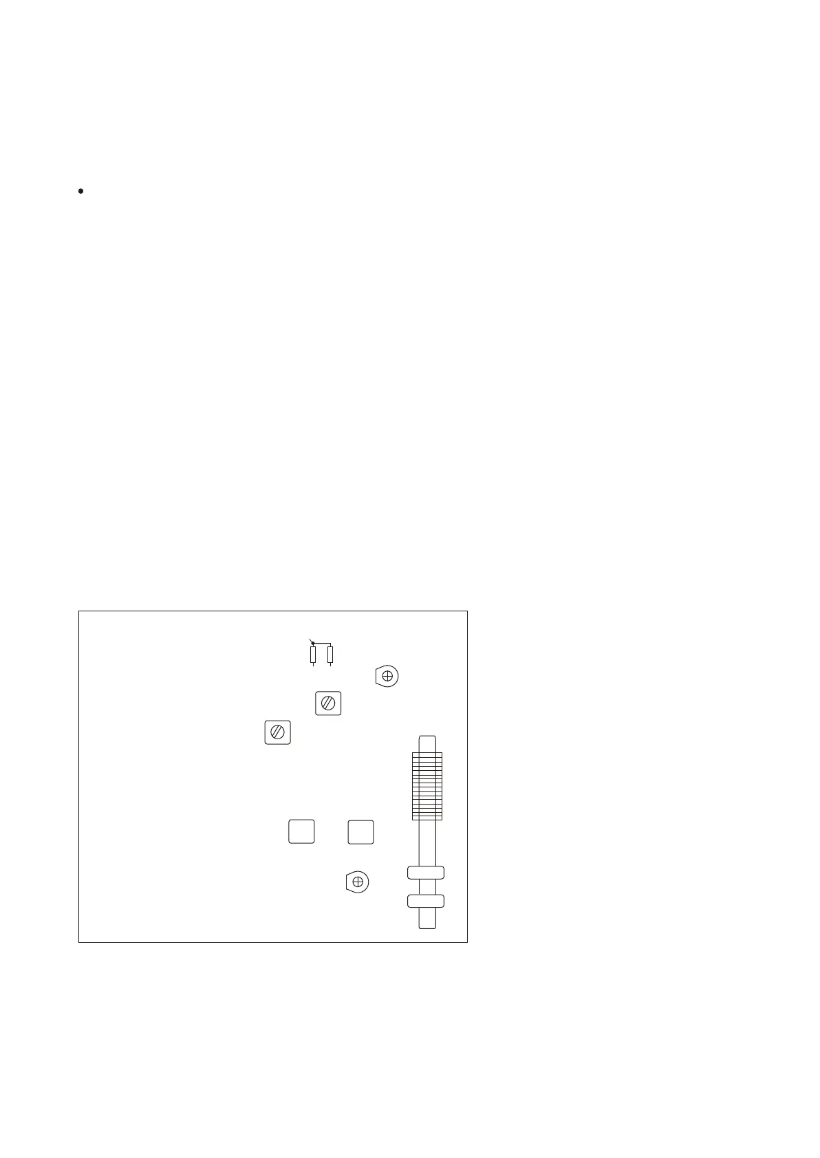
2-2 Adjustment and Test Points
TUNER PCB
TC401
L404
L400
L402 AM ANT COIL
2. Set the BAND switch to the AM position.
2. Set the BAND switch to the FM position.
TC400
L401
L403
VT
R406
R407
6. Set the signal generator as listed in the alignment chart.
6. Set the signal generator as listed in the alignment chart.
5. Connect the digital mulitimeter to R406/R407 on TUNER PCB.