EasyManua.ls Logo

Teac X-10R - 3 Electrical Adjustments and Checks; 3-1 Monitor Performance Checks

Teac X-10R
66 pages
Print Icon
To Next Page IconTo Next Page
To Previous Page IconTo Previous Page
Loading...
10
X-10R/X-10
3
ELECTRICAL
ADJUSTMENTS
AND
CHECKS
NOTES
1.
The
following
data
in
both
the
charts
and
the
illustrations
are
for
the
X-10R.
All
the
procedures,
however,
are
applicable
to
the
X-10
except
for
those
relating
to
the
REVERSE
direction.
2.
Before
performing adjustments
and
checks,
clean
and
demag-
netize
the
entire
tape
path.
3.
Check
that
the
deck
is
properly
set
for
the
voltage
in
your
lo-
cality.
3-1
MONITOR
PERFORMANCE
MONITOR
sw.—
SOURCE
OUTPUT
cont.—
CAL
LINE
cont.-MAX
MIC
cont.—MIN
OSC
>
ATT
to
LINE
IN
(L)
AC
voltmeter
to
VR
PCB
terminal
1.
dbx
level
LINE
spec.
input
level
condition
LINE
IN
(R)
#14
—>
#17
2.
MONITOR
LINE
spec.
output
input
level
level
condition
LINE
spec.
input
level
condition
LINE
cont.—MIN
MIC
cont.—-MAX
Fig.
3-1,
but
LINE
IN
>MIC
4.
MIC
input
level
LINE
cont.—
spec.
position
(Item
1-2)
MIC
cont.—MIN
OSCILLOSCOPE
OSCILLATOR
piSTORTION
ANALYZER
i
or)
ne
AC
Voltmeter
IkHz
FILTER
$2
tL]
DECK
oe?
ca
Lt
under
TEST
7
T-1772
R
LINE
iN
OUTPUT
ATTENUATOR
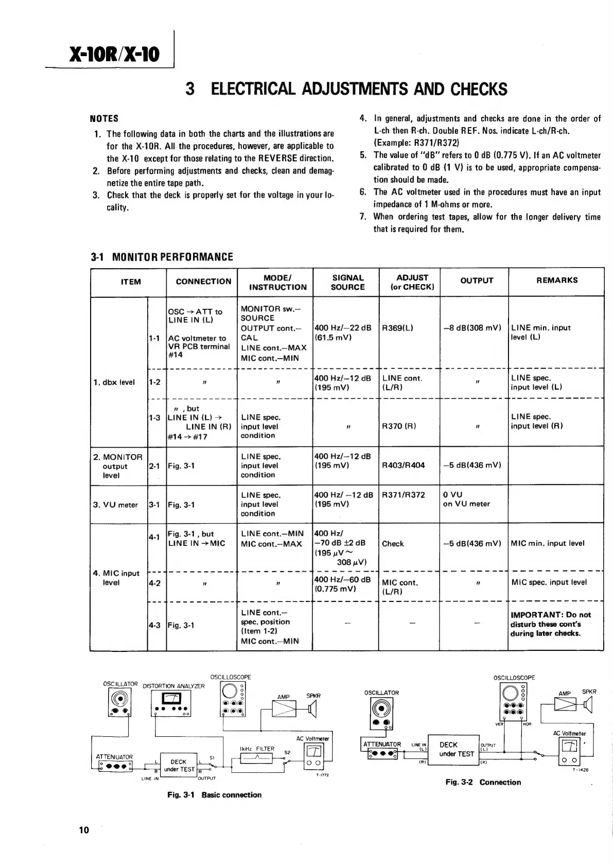
Fig.
3-1
Basic
connection
400
Hz/—22
dB
400
Hz/—12
dB
400
Hz/—12
dB
(195
mv)
400
Hz/
—12
dB
(195
mV)
400
Hz/
—70
dB
+2
dB
(195
uv
~
308
pV)
In
general,
adjustments
and
checks
are
done
in
the
order
of
L-ch
then
R-ch.
Double
REF.
Nos.
indicate
L-ch/R-ch.
(Example:
R371/R372)
The
value
of
“dB”
refers
to
0
dB
(0.775
V).
If
an
AC
voltmeter
calibrated
to
0
dB
(1
V)
is
to
be
used,
appropriate
compensa-
tion
should
be
made.
The
AC
voltmeter
used
in
the
procedures
must
have
an
input
impedance
of
1
M-ohms
or
more.
When
ordering
test
tapes,
allow
for
the
longer
delivery
time
that
is
required
for
them.
R369(L)
—8
dB(308
mV)
|
LINE
min.
input
LINE
cont.
LINE
spec.
input
level
(L)
LINE
spec.
R370
(R)
input
level
(R)
R403/R404
—5
dB(436
mV)
R371/R372
oVvuU
on
VU
meter
400
Hz/—60
dB
(0.775
mV)
IMPORTANT:
Do
not
disturb
these
cont’s
during
later
checks.
OSCILLOSCOPE
OSCILLATOR
AC
Voltmeter
‘
DECK
under
TEST
Fig.
3-2.
Connection
T1428