UK
12
▶ Remove the pallet.
▶ Remove all packaging residue that is affixed to the machine
(adhesive tape, bags, etc.).
▶ Remove the protective film that wraps around the surface
of the machine. This operation may cause irritating electric
shocks despite not posing a hazard (static electricity); this
inconvenience may be reduced or eliminated by keeping
a hand in contact with the machine or by connecting the
external casing to ground.
▶ Carefully remove the glass 1 (Fig. 9) and place it gently in
a safe place for subsequent installation.
9
▶ The machine is equipped with four castors and does not
need to be secured to the floor; locking the castors with the
fasteners to guarantee their stability is su cient.ffi
3.10 MATERIAL SUPPLIED WITH THE SHOW -
CASE
The following standard fittings are available in the internal tray
of the showcase:
! instruction manual;
! laminate assembly (spacers for trays);
! glass superstructure kit (consisting of: side panel assembly
with gaskets in packaging, screw kit, profile);
! Plexiglas flip-up cover.
▶ Remove the supplied fittings from the internal tray and
proceed with the installation as described in the following
section.
4 INSTALLATION
4.1 MOUNTING THE GLASS SUPERSTRUC -
TURE
The machine is delivered with the glass superstructure
disassembled; to secure it to the unit, proceed as follows.
CAUTION! When installing the glass super
structure, only tighten the screws definitively
when the procedure is complete, as adjust
ments may be necessary during the process.
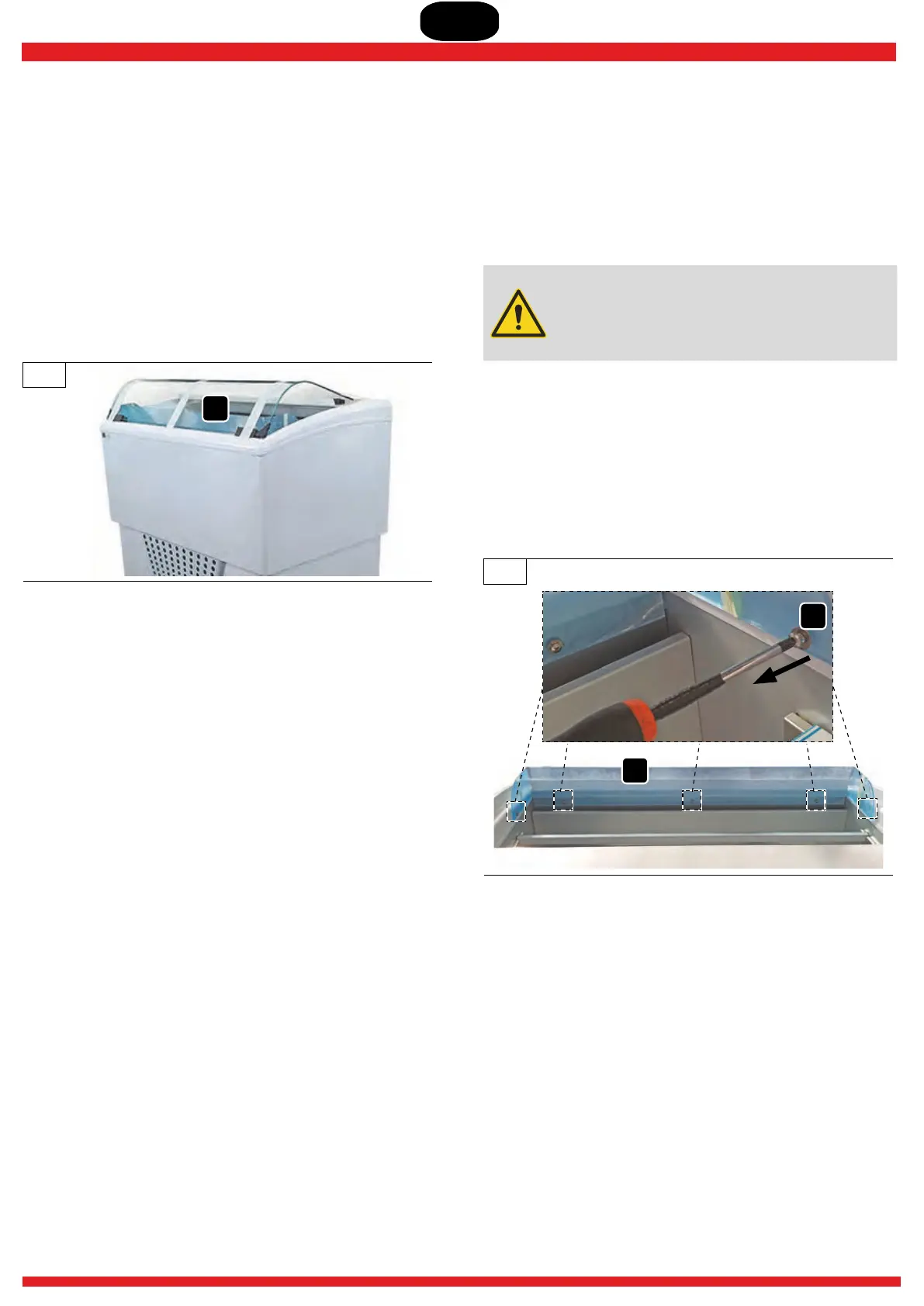
4.1.1 Removing the baffle
▶ Remove the screws V(x 5) and their washers that secure
the baffle to the unit (Fig. 10).
▶ Remove the baffle 2 and remove the corresponding plastic
protection. Store the removed components safely for
subsequent reassembly (excluding the plastic cover).
10
V
2
4.1.2 Installing the side panels
▶ From the supplied fittings use:
! the sides kit 3 and 4 and corresponding gaskets contained
in the packaging and remove them from the latter;
! from the screw kit: 4x long screws and 4x gaskets.
▶ Fasten one side at a time: place sides 3 and 4 in their
respective housings (Fig. 11) and fasten them to the
structure with screws (x2) and gaskets.V
1