UK
14
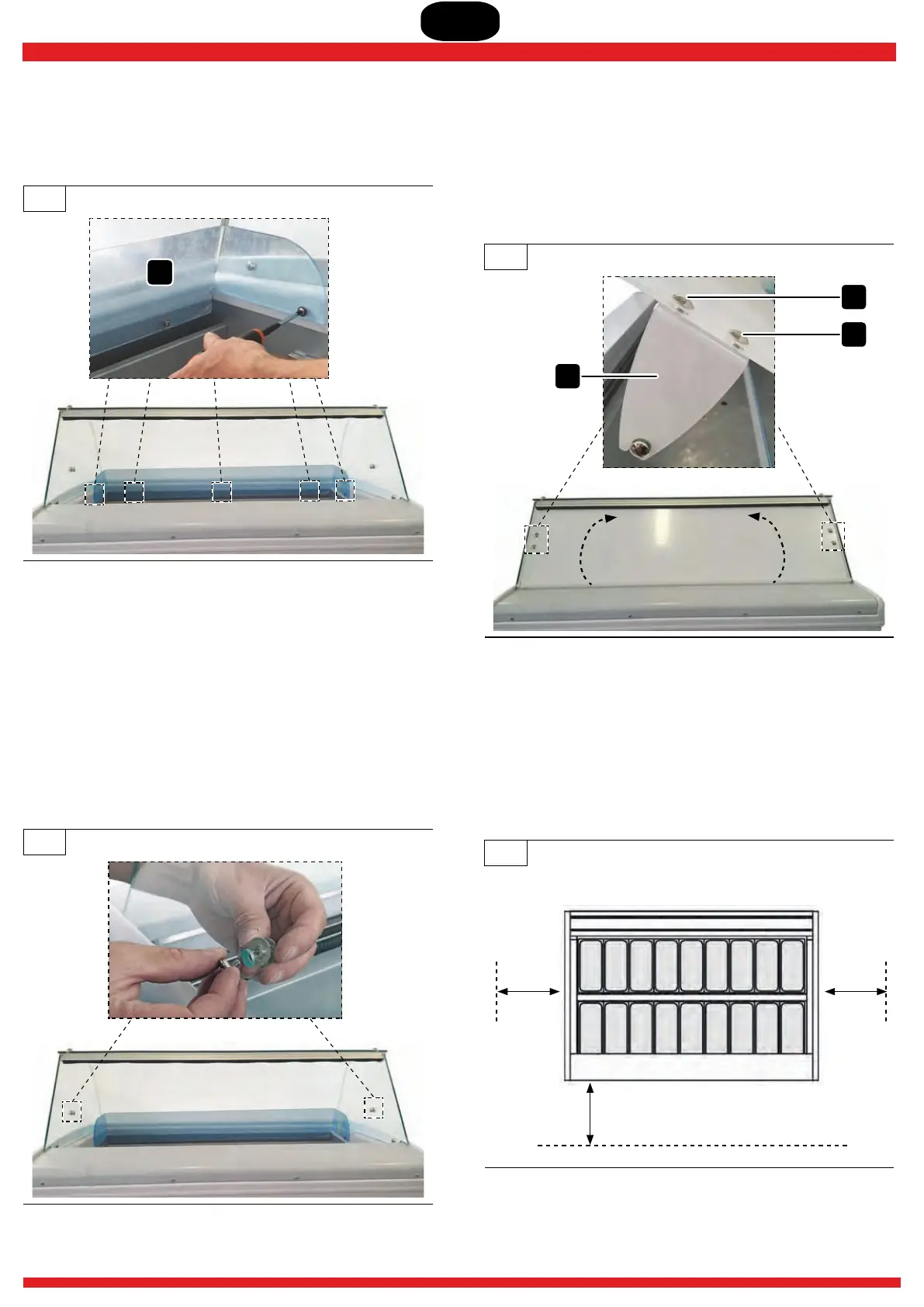
4.1.6 Repositioning the ba effl
▶ Replace the baffle 2 in its housing and secure it with the
corresponding screws and gaskets previously removed.
15
2
4.1.7 Assembling the Plexiglas flip-up cover
▶ From the supplied fittings use:
! Plexiglas flip-up cover kit and remove the packaging;
! from the screw kit: 6x short screws, 6x gaskets, 2x pins for
the flip-up cover.
▶ Secure the pin to the short screw and gasket in the holes
provided on the side panels. The pin must be installed
from the inside of the side as shown in the figure.
16
▶ Position the rotation arms B in line with the holes provided
on the flip-up cover and secure them with screws V (x4)
and gaskets.
▶ Position the grooves of the rotation arms into the pins
located on the side panels and check that the flip-up cover
moves correctly.
17
B
V
V
4.2 OPERATING AND MAINTENANCE AREA
▶ Position the machine in the final installation area.
▶ Leave a sufficiently clear area of at least 1 metre per side
(minimum) to perform the necessary maintenance and
procedures in complete safety.
18
1 m
1 m
1 m
Customer side
RIGHT
SIDE
LEFT
SIDE
OPERATOR SIDE