⚫ in well ventilated areas.
Please be sure not to cover the vents.
Connecting the inverter
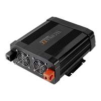
This Inverter has two DC cable connections, one positive and one negative.
The order of steps in the following procedure minimizes the danger of sparking
near the battery bank.
⚫ Prepare all cable set ends with ring terminals at the battery ends
⚫ Select the OFF position on the inverter
⚫ Remove the red positive(+) screw connector cap
⚫ Slide the red positive(+) cable lead onto the red positive(+) screw connector
stud. Tighten the screw connector cap securely
⚫ Remove the Black negative(-) screw connector cap
⚫ Slide the Black negative(-) cable lead onto the Black negative(-) screw
connector stud. Tighten the screw connector cap securely
⚫ Securely connect the red positive (+) cable lead to the positive (+) terminal
of the battery or power source
⚫ Securely connect the black negative (-) cable lead to the negative (-)
terminal of the battery or power source
⚫ Connect a 2.00mm² wire or larger insulated wire between the chassis
ground connector on the Inverter and a clean electrical grounding point on the
vehicle. This will minimize possible electrical noise interference when using
TVs or radios.
Note: Sparking is normal for first connection.
Operation
Before using the power inverter determine your equipment’s total watts!
⚫ Do not connect more watt than the Output Power (maximum continuous
watt) of the device (➔ see technical specifications).
⚫ Determine Total Wattage Required, Watt ratings are usually listed in
equipment manuals or on nameplates. If your equipment is rated in Amp,
multiply that number times AC utility voltage to determine watts.
(mathematic example: a drill requires 1.5A → 1.5A x 230Volt = 345Watt. → No
problem to use the drill.)
⚫ Remember the vehicle‘s battery will be discharged when the vehicle is not
running.