EasyManua.ls Logo

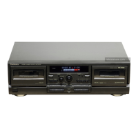
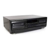
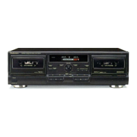
Technics RS-TR474

Technics RS-TR474
50 pages
To Next Page IconTo Next Page
To Previous Page IconTo Previous Page
Loading...
HEAD
REPLACEMENT
When
replacing
the
R/P
head
or
E
head,
adjust
the
head
azimuth
(erase
head
with
small
screw
stop
does
not
need
adjustment)
then
start
the
EEPROM
adjustment
in
the
following
sequence.
;
(1)
(2)
(4)
(3)
(The
adjustment
is
necessary
because
the
playback
gain,
the
overall
gain,
and
the
overali
frequency
response
are
changed
by
the
head
replacement.)
HEAD
AZIMUTH
ADJUSTMENT
(DECK
1/2)
4.
Playback
the
azimuth
adjustment
portion
(8kHz,
—20dB)
of
the
test
tape
(QZZCFM).
Vary
the
azimuth
adjusting
screw
until
the
output
of
the
R-CH
are
maximized.
.
Perform
the
same
adjustment
in
the
play
mode.
.
Repeat
the
same
check
in
reverse
play
mode.
.
After
the
adjustment,
apply
screwlock
to
the
azimuth
adjust-
E.HEAD
R/P.
HEAD
ing
screw.
pn
(playback)
Azimuth
Screw
Azimuth
Screw
:
(Forward)
(Reverse)
TAPE
SPEED
ADJUSTMENT
(DECK
1/2)
Normal
speed
1.
Playback
the
middle
portion
of
the
test
tape
(Q2ZZCWAT).
2.
Short
the
test
terminal.
3.
Adjust
Deck
1=VR801
and
Deck
2=VR803
so
that
the
output
is
within
the
standard
value.
LINE
OUT
Standard
value:
3000
+15Hz
(NORMAL
speed)
puis
requency
counter
High
speed
[Set
the
unit
to
forward
(FWD)
mode.]
4.
Press
the
tape-to-tape
recording-speed
selector
switch
(X2)
button.
This
will
set
the
high
speed
mode.
5.
Playback
the
middle
portion
on
the
test
tape
(QZZCWAT).
6.
At
that
time,
check
if
the
output
from
DECK
1
is
within
the
standard
value.
Standard
value:
6000+600Hz
(HIGH
speed)
.
Adjust
VR802
so
that
the
output
frequency
of
DECK
2
is
within
+30Hz
for
the
value
of
the
output
frequency
of
DECK
1.
.
Release
the
test
terminal.
PLAYBACK
GAIN
MEASUREMENT
(DECK
1/2)
4.
Load
the
test
tape
(QZZCFM)
into
the
deck
and
locate
UNE
OUT
the
part
where
the
playback
gain
test
tone
(815Hz,
OdB)
is
recorded.
After
this,
play
back
the
tape
and
verify
that
the
output
level
fails
in
the
specified
range.
Standard
value:
320mV+0.5d8
2.
If
outside
the
standard
value,
data
in
EEPROM
should
be
written
again
by
taking
the
following
procedure
and
there
thereafter
section
1
should
be
carried
out
again.
(1)
(2)
(3)
Step
1
on
page
19
Step
5
on
page
20
Step
10
on
page
21

Other manuals for Technics RS-TR474

Related product manuals