9. Block Diagram
10. Schematic Diagram
(All schematic diagrams may be modified at any time with the development of new technology.)
Notes:
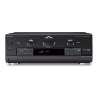
S950 Power Switch
S951 Speaker A Switch
S955 Memory Switch
S956 FM Mode Switch
S957 Band Switch
S958 Preset Switch
S959 Tuning Up Switch
S960 Tuning Down Switch
S961 Speaker B Switch
S962 Help Switch
S963 DSP. Sound Mode Switch
S965 Digital Switch
S966 DVD 6CH Switch
S967 +/Right Switch
S968 -/Left Switch
S969 Tone/Balance Switch
S970 Tape Monitor Switch
S971 Sub. Woofer Level Switch
VR901 Input Selector Knob
VR902 Volume Knob
VR903 SFC Mode Knob
- The voltage value and waveforms are the reference voltage of this
unit measured by DC electronic voltmeter (high impedance) and
oscilloscope on the basis of chassis. Accordingly, there may arise
some error in voltage values and waveforms depending upon the
internal impedance of the tester or the measuring unit.
< > ...FM
- Importance safety notice:
Components identifed by mark have special characteristics
important for safety. Furthermore, special parts which have
purposes of fire-retardant (resistors), high-quality sound
(capacitors), low-noise (resistors), etc. are used. When replacing
any of components, be sure to use only manufacturer’s specified
21

 Loading...