Do you have a question about the Technics SA-EH790E and is the answer not in the manual?
Comprehensive technical specifications including amplifier, tuner, and timer functions.
Critical safety warnings for technicians and general handling precautions.
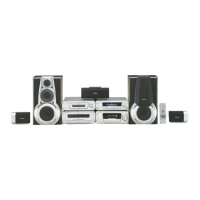
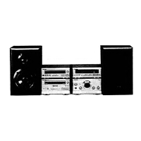
Lists all components included in the SC-EH790 system.
Explains protection circuitry function and lists unit accessories.
Safety instructions for AC mains lead handling and fuse replacement.
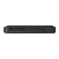
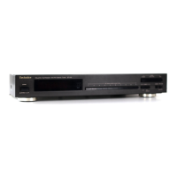
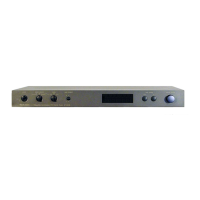
Identifies the location and function of unit controls.
Guidance on checking operation and replacing main components.
Steps for checking AC IN and Operation Printed Circuit Boards.
Steps for replacing regulator transistor and power IC.
Method for supplying power for testing and information on self-diagnosis.
How to display malfunction codes and return to normal operation.
Notes on diagrams and terminal functions of integrated circuits.
Comprehensive list of replaceable parts with part numbers.
Diagram showing the location of cabinet parts.
Explains the function of each button and control on the front panel.
| Tuner Type | Digital |
|---|---|
| Tuning bands | FM, MW |
| FM Tuning Range | 87.5 - 108 MHz |
| MW Tuning Range | 522 - 1611 kHz |
| Number of Preset Stations | 39 |
| Signal-to-Noise Ratio (FM) | 70 dB |
| Signal-to-Noise Ratio (MW) | 50 dB |
| Distortion (MW) | 0.5% |
| Frequency Response (FM) | 30 Hz - 15 kHz |
| FM Usable Sensitivity | 1.5 µV (IHF) |
| Output Level | 500 mV |
| Distortion (FM) | 0.3% |