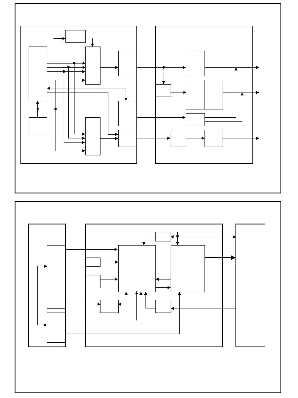
DZ1200 audio output circuit block diagram
Fig 5
MAIN JACK
IC18
+7 V power supply
Three-terminal
+5 V for audio
regulator
IC14 IC33
Scratch microcomputer
DAC IC35 IC2004
DSC25
PCM1734
Operation Operation
LRCK Analog amplifier Analog amplifier Analog
DATA audio M5218A audio M5218A audio LINE
BCK OUT
SCK
IC2002 Q2004
Serial communication VR2002 Operation Q2005 H.PHONE
Digital output enable signal H.PHONE
amplifier Q2006 audio H.PHONE
VR M5218A Q2007 OUT
IC2
UI microcomputer
M30622
MUTE signal MUTE
X6 IC4 circuit
11.2896MHz
DIGITAL
AUDIO
TC9271 IC15 Digital IC2006 T2001 Digital
Gate audio 7WU04F Isolation audio DIGITAL
7W08F Buffer
transformer
OUT
DZ1200 turntable control circuit block diagram
Fig 6
JACK +20V
+10V Q2008
Transistor
Clock TT.PWM
IC2
UI microcomputer
Three-phase signal
Serial M30622 X2001
communication
4.193MHz
Brake ECR
adjustment
VR2001 EC
Torque switching
IC2007 Q2009
IC2008 FG FG signal FD coil
Analog SW
AMP
IC14
Scratch microcomputer
Motor ON/OFF
DSC25 Turntable FREE
+20 V power supply
MAIN Turntable
Refer to the item "Signal flow", turntable.
Refer to the item "Signal flow", CD, SD audio flow.
Motor
IC2003 IC2005
Motor controller Motor driver
AN6680 AN6675
Forward/reverse switching signal