Do you have a question about the Technics SX-KN7000P and is the answer not in the manual?
Procedure to measure electrical resistance for safety checks to prevent electric shock hazards.
Details on MIDI message transmission and reception capabilities.
Information on the instrument's keyboard note ranges and touch response.
Diagrams indicating the location of various parts within the instrument.
Steps to remove the top housing of the keyboard.
Procedures for removing internal PCBs like JACK, MAIN, FAJ, ACP, LCD, CPL, etc.
Steps for removing Disk Drive, Power SW, Speakers, and Keys.
Tests for ROM and RAM device integrity.
Tests for Panel, LCD, MIDI, SD card, and Sound System functionality.
Guidelines for handling Flash ROM, including replacement and data writing.
Precautions and methods for measuring output waveforms using an oscilloscope.
Critical safety warnings regarding components and general servicing.
Explanation of symbolic marks for resistors and capacitors used in circuits.
| Brand | Technics |
|---|---|
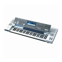
| Model | SX-KN7000P |
| Category | Electronic Keyboard |
| Language | English |