No. PCB TEST MODE Procedure
2 CPL CPU (IC1) check 1. Connect the CHECKING DEVICE to CN9 on the MAIN
Checking Device switch should be off).
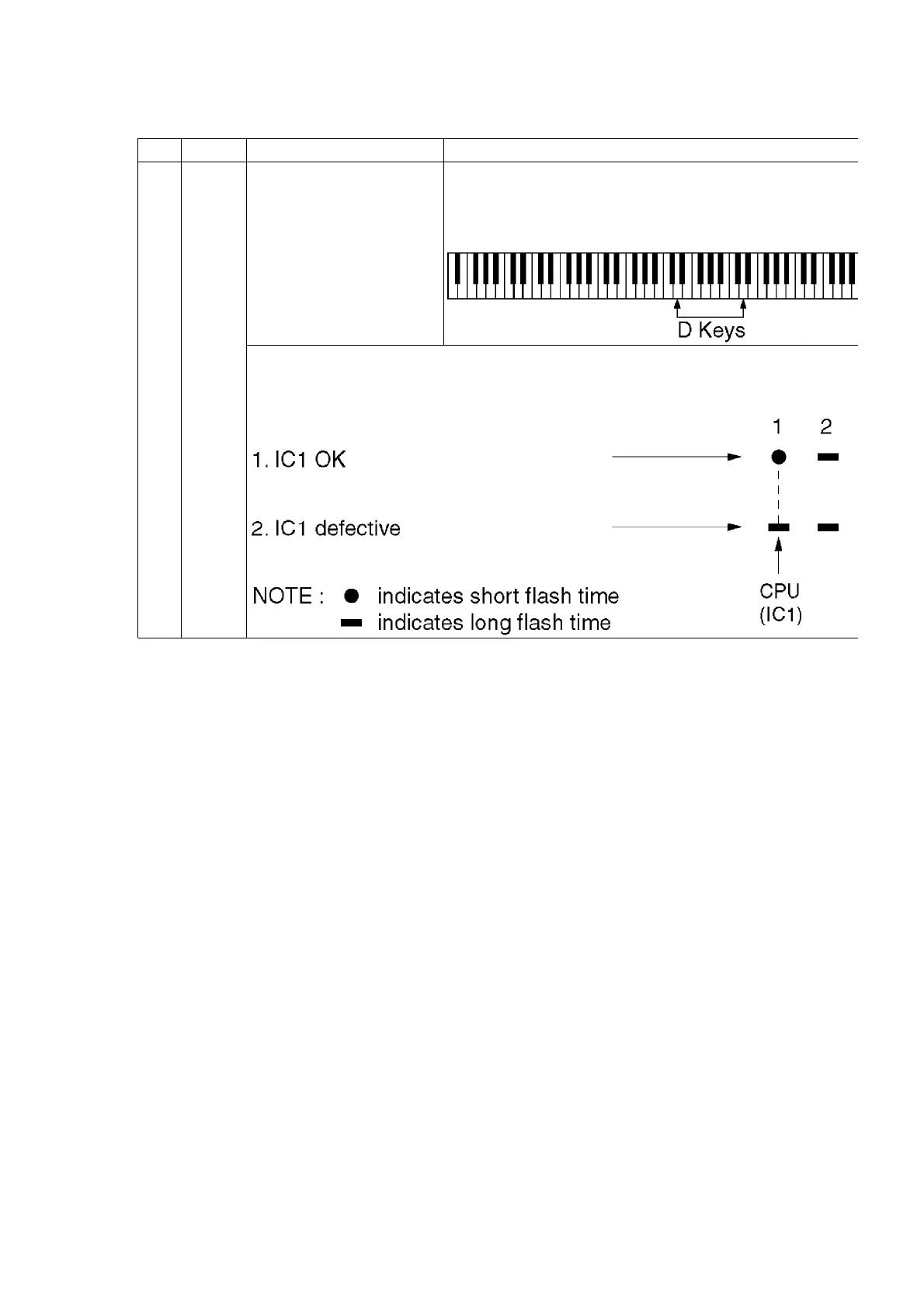
2. Press and hold the two D keys shown below, and
the power switch.
When the power switch is turned on, the LED of the CHECKING DEVICE flashes 4
order of the LED flashes corresponds to the CPU (IC) on the respective P.C.B.s as
below. If an IC isdefective, the corresponding flash time is longer.
13
 Loading...