(Step2)
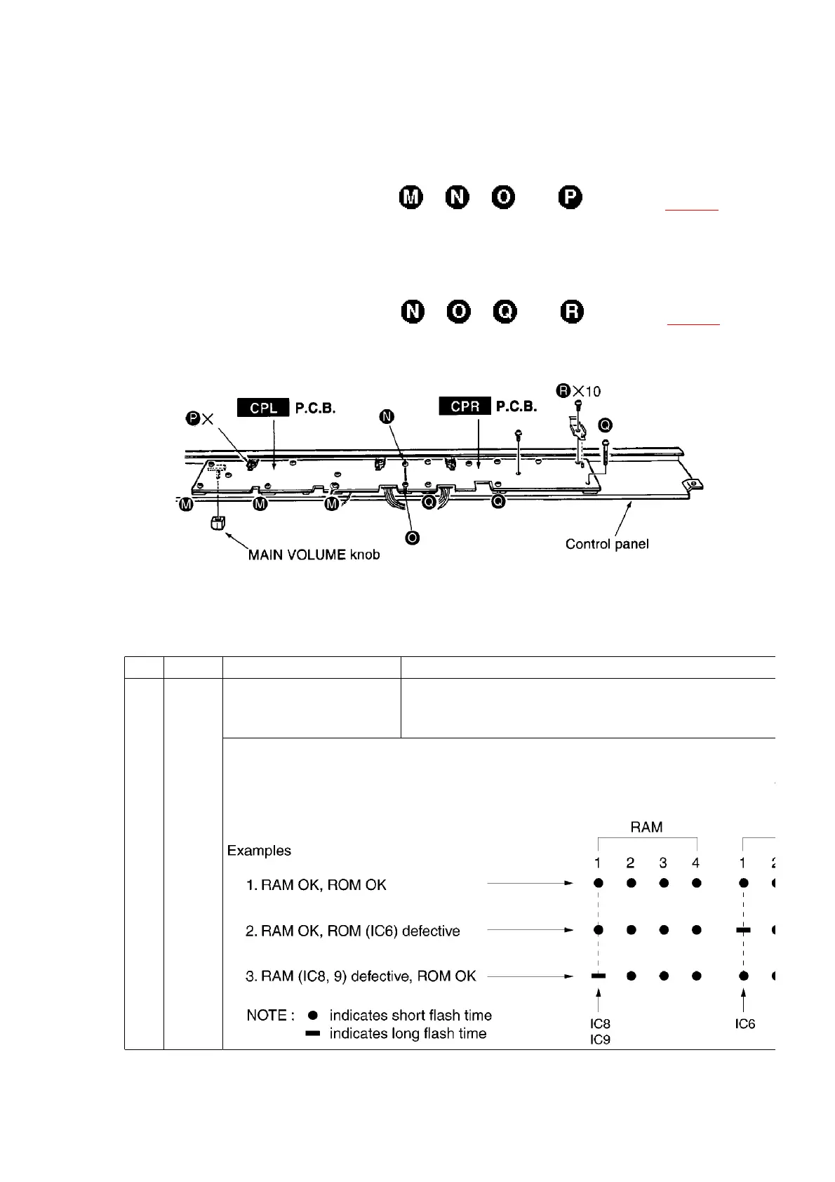
Remove the CPL P.C.B. mounting screws ×3, ×1, ×1and ×10 (refer to [Fig. 11] ).
- CPR P.C.B.
(Step1)
Remove the CPR P.C.B. mounting screws ×1, ×1, ×3and ×10 (refer to [Fig. 11] ).
[Fig. 11]
11. About the Self-Diagnostic Function
This model has some self-diagnostic capabilities. When set to the self-diagnostic mode,
operation of various components can be verified by following the procedures in the chart below.
No. PCB TEST MODE Procedure
1 MAIN RAM (IC8, 9), ROM (IC6)
check
1. Connect the CHECKING DEVICE to CN9 on the MAIN
turn on the CHECKING DEVICE switch.
2. Turn on the power switch.
When the power switch is turned on, the LED of the CHECKING DEVICE flashes 8
first 4 flashes are for the RAM check , and the latter 4 flashes are for the ROM
order of theLED flashes correspond to the respective IC numbers as shown below.
defective, the corresponding flash time is longer.
12
 Loading...