C
Ref. 72523 - XM700_en_B
13/23
CInstallation
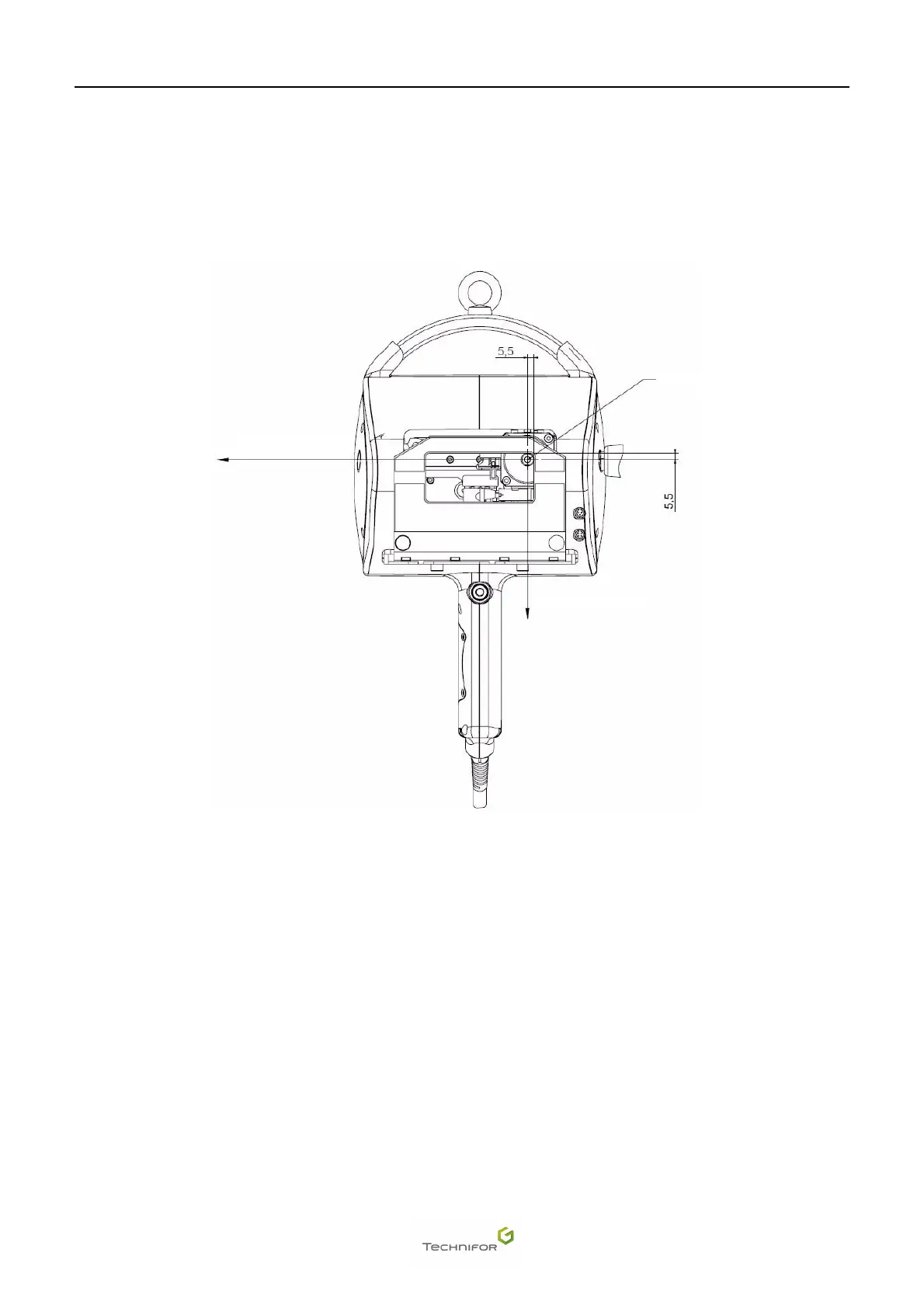
1. Coordinate system
The coordinate system used in our machines is shown in the following diagram.
The origin position is defined by the dimensions of 5.5 mm (0.217 in) (dimensions between the point axis and the
edge of the window). Tolerance: +/- 1 mm (0.039 in)
Coordinate system
1 : Stylus: origin
2 : X axis - Travel distance 80 mm (3.15 in)
3 : Y axis - Travel distance 30 mm (1.181 in)
The coordinates are given as absolute coordinates in relation to the origin position.
With the marking gun held in front of the operator:
• X axis: horizontal axis going from left to right
• Y axis: descending vertical axis
When a marking cycle is launched, the stylus always begins at the origin point and returns to the origin at the end
of the cycle.
When the marking gun is held against the part to be marked, do not apply excessive pressure on the handles.
This risks causing flexion and an incorrect distance between the part and the point.
Note: The optimal distance between the point and the part to be marked (adjustment along Z) that allows the use
of all marking force percentages is 6 mm (0.236 in). This distance is factory-set when the base is attached.
Force percentages between 1 and 10% are reserved for very fine marking.
1
2
3