C
Copyright Technolog Ltd. 2017. All rights reserved.
Information contained in this document subject to
change without prior notice.
Sheet 8 of 43
Technolog Limited,
Ravenstor Road,
Wirksworth,
DE4 4FY,
United Kingdom
T: +44 (0) 1629 823611
E: techsupport@technolog.com
www.technolog.com
DMR No.: 7504
2099PM9000 Rev. B
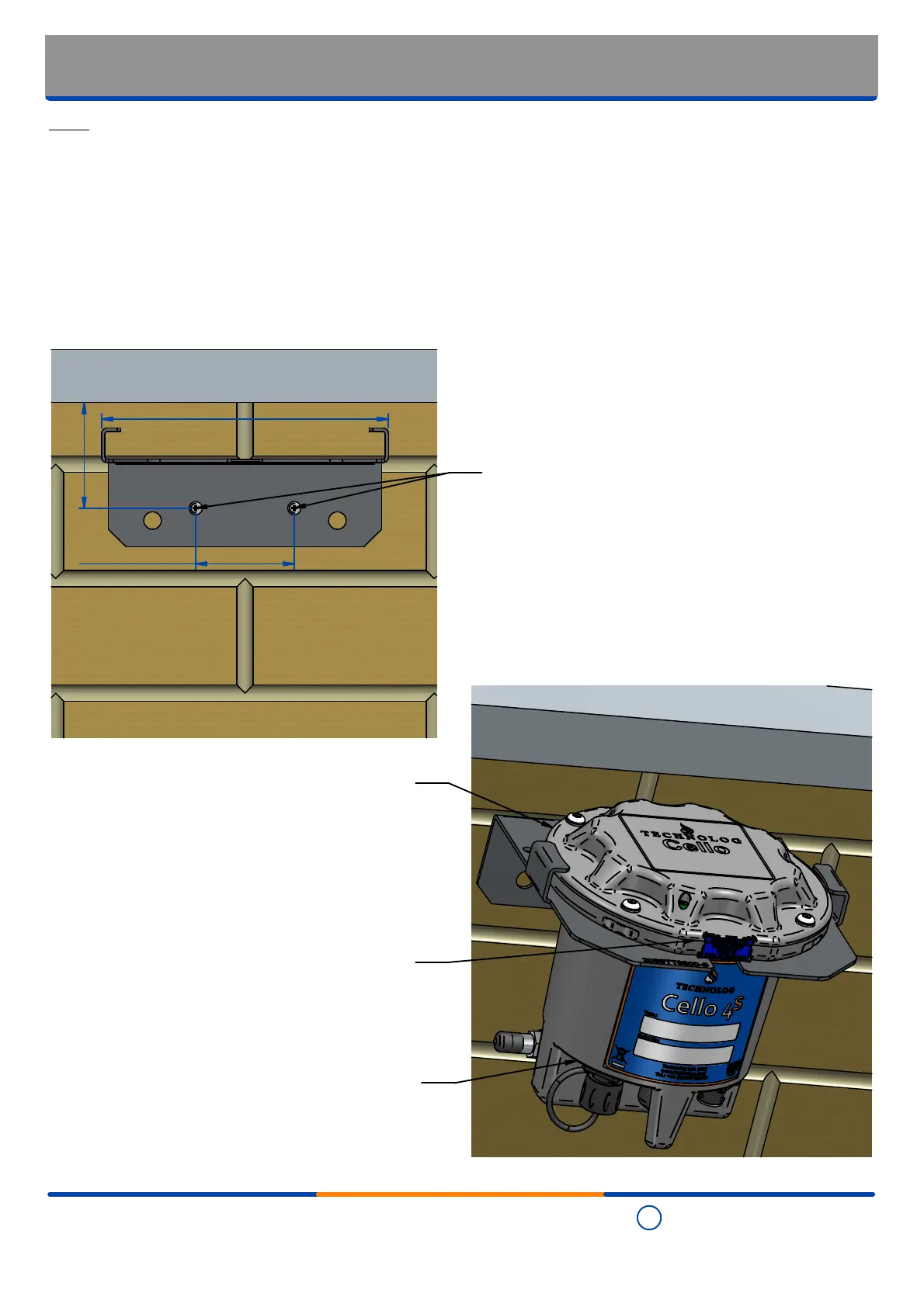
Typical installation: Stainless steel wall bracket
(p / no. 2099TT6500)
Notes
In order to maximise the remote communications signal strength, the unit should be positioned as
high up as possible and, where practical, away from metal structures.
However the unit should also be positioned such that exposure of users and / or bystanders to the
potentially dangerous radio frequencies ('RF') generated by the equipment are kept below
recommended levels - for further details refer to Technolog Declaration of Conformity ('D of C')
document 2099DC9000 associated with the Cello 4S, as well as the "RF exposure onsiderations"
part of the "Standard connections - Port 5: External antenna connection" section of this
document.
•
•
163 mm
Step 2a
Carefully fit the unit partially in the
bracket
Step 2b
Rotate the unit until the 'flats' on
the lid are aligned with the 'tabs''
on the bracket
60 mm min.
Step 1
Drill two holes in the positioons indicated
to take 'Rawl' plugs suitable for 1" x 8mm
(or equivalent) screws
Step 2c
To secure the unit in place, rotate
it until it is positioned as shown
56 mm centres