9
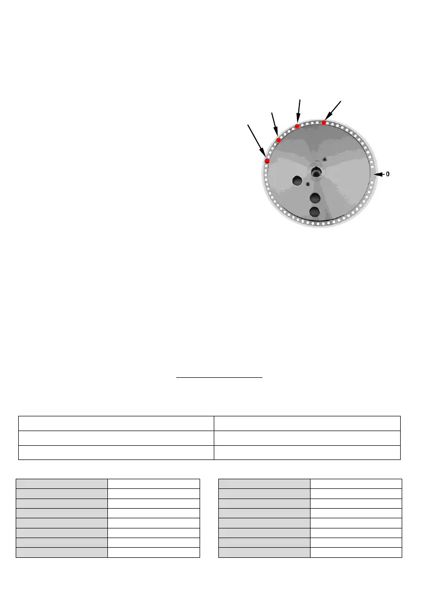
Place and number the pins as follows:
The pins are 4, corresponding to the 4 different angles (make some tests to find out the correct position).
Place as in the picture, considering that the rotation direction is clockwise:
The pin at 60° is n° 1 (the numbering starts with the one nearest the limit switch).
The pin at 90° is n° 2
The pin at 120° is n° 3
The pin at 135° is n° 4
Panel-programming for the
bending sequence:
a) Push the button for programme activation-
deactivation: the light is on and the
programme is active.
b) Using the bending buttons select 1 (1° bending)
and using the pin buttons select 4
(n° of the pin corresponding to the 1° bending).
c) Repeat the operations for the following
bendings:
• Bending 2 pin 2
• Bending 3 pin 3
• Bending 4 pin 1
• Bending 5 pin 4
d) The programme ends when the 6° bending is selected on 0.
e) Push the button for programme activation-deactivation: the light is off and the programme is not
active.
f ) Keep the RESET button pressed for 4÷5 sec. and start the programme with the 1° bending.
Bending repetition
a) Push the button for programme activation-deactivation (light on).
b) Using the bending buttons select the required bending.
c) Push the button for programme activation-deactivation (light off).
d) Push the pedal to execute the chosen bending. The programme goes on with the next bending.
Push RESET for 4÷5 seconds to start the programme with the 1° bending.
9 Limitations on the use
9.1 European legislation UNI EN 1992-1-1 Chapter 8 - paragraph 8.3
Minimum diameter of the mandrel to avoid damages to the concrete:
Minimum diameter of the mandrel
Mandrel table