1.
INTRODUCTION
This section provides description and operation
of
the aircraft and its systems.
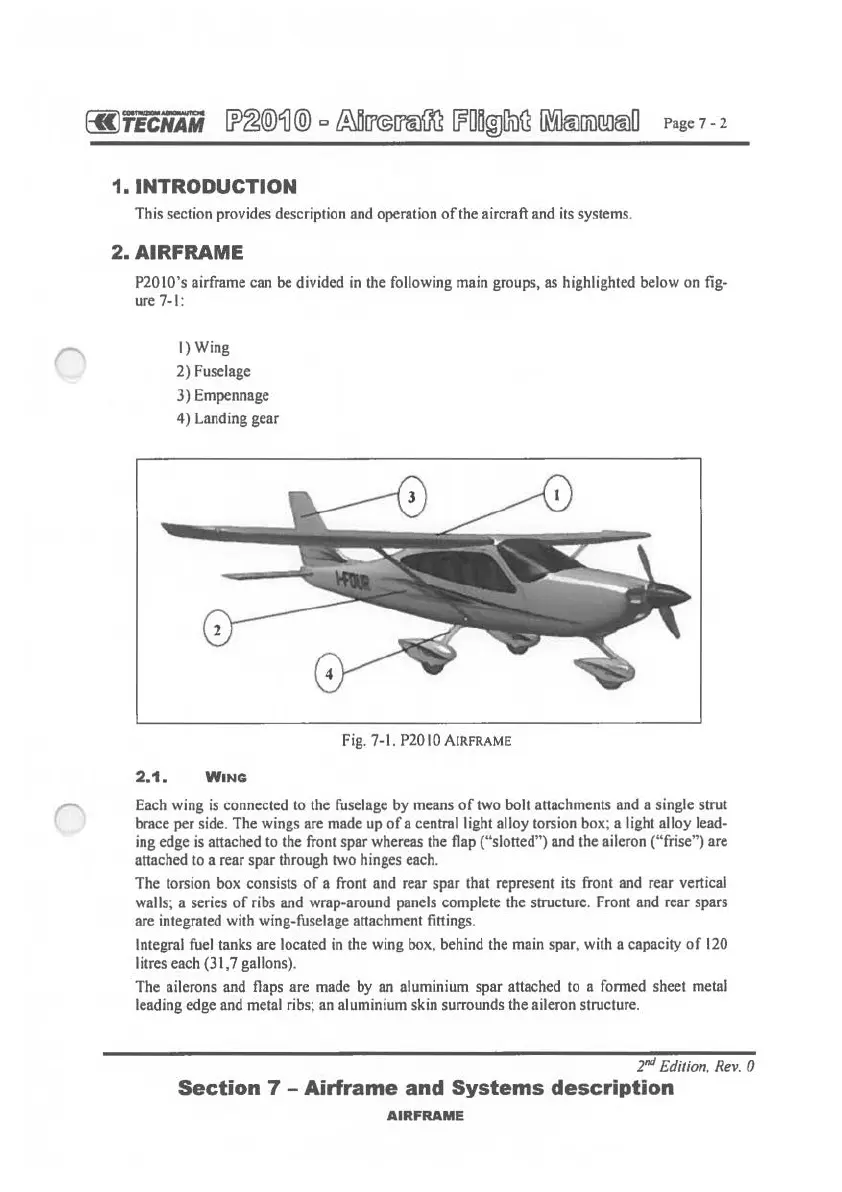
2.AIRFRAME
P20JO's airframe can be divided
in
the following main groups, as highlighted below on fig-
ure 7-1:
I)
Wing
2) Fuselage
3) Empennage
4) Landing gear
Fig. 7-1. P20IOAIRFRAME
2.1.
WING
Each wing
is
connected to the fuselage by means
of
two bolt attachments and a single strut
brace per side. The wings are made up
of
a central light alloy torsion box; a light alloy lead-
ing edge
is
attached to the front spar whereas the flap ("slotted") and the aileron ("frise") are
attached to a rear spar through two hinges each.
The torsion box consists
of
a front and rear
spar
that represent its front and rear vertical
walls; a series
of
ribs and wrap-around panels complete the structure. Front and rear spars
are integrated with wing-fuselage attachment fittings.
Integral fuel tanks are located in the wing box, behind the main spar, with a capacity
of
120
litres each (31,7 gallons).
The ailerons and flaps are made by an aluminium spar attached to a formed sheet metal
leading edge and metal ribs; an aluminium skin surrounds the aileron structure.
2"d
Edition, Rev. 0
Section
7 -
Airframe
and
Systems
description
AIRFRAME
 Loading...