8.
FUEL
SYSTEM
The fuel system
is
designed to supply the reciprocating engine with the suitable
flow rate and pressure according to engine limitations required by Lycoming op-
erator manual.
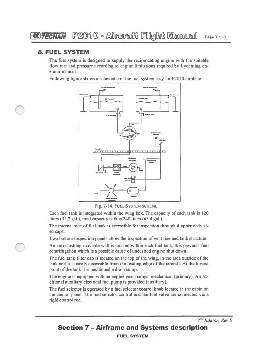
Following figure shows a schematic
of
the fuel system assy for P2010 airplane.
Fig.
7-14.
FUEL
SYSTEM SCHEME
Each fuel tank is integrated within the wing box. The capacity
of
each tank
is
120
liters (31,7 gal.), total capacity is thus 240 liters (63.4 gal.).
The internal side
of
fuel tank
is
accessible for inspection through 4 upper dedicat-
ed caps.
Two bottom inspection panels allow the inspection
of
vent line and tank structure.
An anti-sloshing movable wall
is
located within each fuel tank, this prevents fuel
centrifugation which
is
a possible cause
of
undesired engine shut down.
The fuel tank filler cap
is
located on the top
of
the wing,
in
the area outside
of
the
tank and
it
is
easily accessible from the leading edge
of
the aircraft. At the lowest
point
of
the tank
it
is positioned a drain sump.
The engine
is
equipped with an engine gear pumps, mechanical {primary). An ad-
ditional auxiliary electrical fuel pump is provided (auxiliary).
The fuel selector is operated by a fuel selector control knob located
in
the cabin on
the central panel. The fuel selector control and the fuel valve are connected via a
rigid control rod.
2"
d Edition, Rev 5
Section
7 -
Airframe
and
Systems
description
FUEL
SYSTEM