2.3.1.
RUDDER
SURFACE
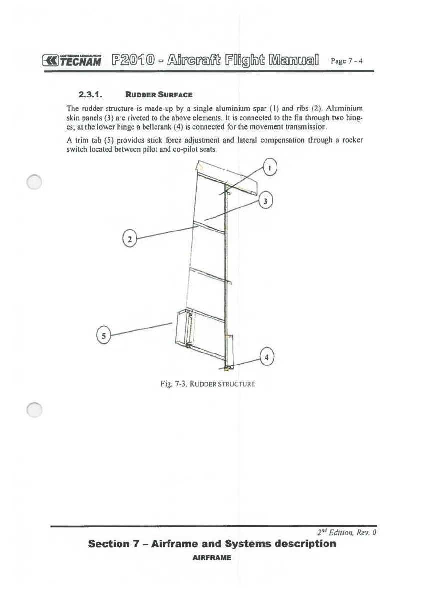
The rudder structure
is
made-up
by
a single aluminium spar
(I)
and ribs (2
).
Aluminium
skin panels (3) are riveted
to
the above elements.
It
is
connected
to
the fin through two hing-
es; at the lower hinge a bellcrank (4)
is
connected for the movement transmission.
A trim tab (5) provides stick force adjustment and lateral compensation through a rocker
switch located between pilot and co-pilot seats.
Fig. 7-3. R UDDER STRUCTURE
2•" Edition, Rev. 0
Section
7 -
Airframe
and
Systems
description
AIRFRAME
 Loading...