P.A. : All Alarm outputs (A1, A2, HB) have to be of the same type (all
Relay or all 24 VDC for SSR driving )
2 - TECHNICAL DATA
ELECTRICAL DATA
Supply:
24 VAC/VDC, 90 ... 240 VAC +/- 10%
Frequency
AC: 50/60 Hz
Power
consumption: 7 VA approx.
Input/s:
1 input for temperature probes (tc J, K, R, S, T; RTD Pt 100 IEC).
1 input for current transformer with K = 1/0,002 (Max. 200 mA)
Output/s:
Up to 5 outputs. Relay (5 A-AC1, 2 A-AC3 / 250 VAC), 10 A Max
per common (pin 12); or voltage for SSR drive (24VDC/0mA,
14VDC/20mA)
Electrical
life for relay output : 100000 operat.
Protection
class against electric shock: Class II for Front panel
Insulation:
Reinforced insulation between the low voltage section (supply
and relay outputs) and the front panel; Basic insulation between the low
voltage section (supply and relay outputs) and the extra low voltage section
(inputs and outputs for SSR); No insulation between inputs and outputs for
SSR .
MECHANICAL DATA
Housing:
Self-extinguishing plastic, UL 94 V0
Dimensions:
48 x 96 mm DIN, depht 100 mm
Weight:
290 g approx.
Mounting:
Flush in panel in 45 x 92 mm hole
Connections:
6.3 mm Faston terminals
Degree
of protection of front panel : IP 54 mounted in panel with gasket
Pollution
situation: Normal
Operating
temperature: 0 ... 55 °C
Operating
humidity: 30 ... 95 RH% without condesation
Storage
temperature: -10 ... +60 °C
FUNCTIONAL DATA
Control:
ON/OFF, PID
Measurement
range: according to the used probe (see table range)
Display
resolution: according to the probe used 1/0,1
Overall
accuracy: +/- 0,25 % fs
Sampling
rate: 1 sample per second
Action:
1C type according to EN 60730-1
Compliance:
ECC directive EMC 89/336 (EN 50081-1, EN 50082-1), ECC
directive LV 73/23 and 93/68 (EN 60730-1)
MEASUREMENT RANGE TABLE
Pt2
-99.9 ... 850.0 °C
-99.9 ... 999.9 °F
73.0 ... 999.9 K
Pt1
-200 ... 850 °C
-328 ... 1562 °F
73 ... 1123 K
RTD Pt100 IEC
(Pt1, Pt2)
- - - -200 ... 400 °C
-328 ... 752 °F
73 ... 673 K
tc T
(t)
- - - -50 ... 1760 °C
-58 ... 3200 °F
223 ... 2033 K
tc S
(S)
- - - 0 ... 1760 °C
32 ... 3200 °F
273 ... 2033 K
tc R
(r)
- - - -200 ... 1370 °C
-328 ... 2498 °F
73 ... 1643 K
tc K
(CrAl)
- - - -200 ... 870 °C
-328 ... 1598 °F
73 ... 1143 K
tc J
(J)
4 DIGIT with D.P.4 DIGIT PROBE
3 - INSTALLATION
MECHANICAL MOUNTING: The instrument, in DIN case 48 x 96 mm,
is designed for panel mounting. Make an hole 45 x 92 mm and insert the
instrument, fixing it with the provided special brackets . We recommend to
mount the gasket to obtain an IP 54 front protection. Avoid to place the
instrument in areas with humidity or dirt. Connect the instrument as far as
possible from source of electromagnetic disturbances so as motors, power
relays, relays, electrovalves,etc. The instrument is removable from its
housing by the front side : is recommended to disconnect the power supply
from the instrument when is necessary to do this operation.
ELECTRICAL CONNECTIONS: Carry out the electrical wiring
connecting only one wire for each terminal , according to the following
diagram, check that the power supply is the same as indicated on the
instrument and the loads current is not upper than the maximum current
admitted. The instrument, being a built in equipment with permanent
connection into a cabinet, is not furnished with internal device protecting
from overcurrent : it's recommended , therefore, to properly protect all the
electric circuits connected to the instrument, with devices (ex. fuses)
proportionate to the circulating currents. It's strongly recommended to use
cables with proper insulation, according to the working voltages and
temperatures. Furthermore, the input cable of the probe has to be kept
separate from line voltage wiring. If the input cable of the probe is
screened, it has to be connected on the ground with only one side. It is
advisable to check that the parameters are those desired before connecting
the outputs to the actuators so as to avoid malfunctioning . Whenever a
failure of the instrument could cause dangerous or damaging situations, it
should be kept in mind that the plant has to be provided with additional
devices to ensure the safety.
4 - OPERATING MODE
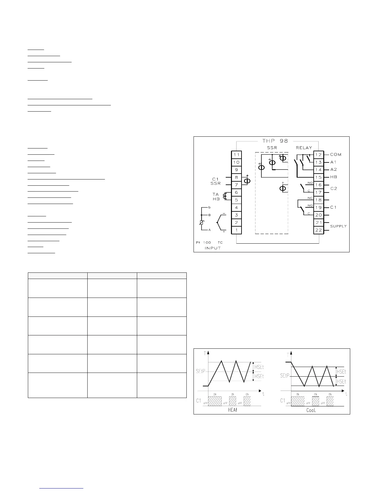
4.1 - ON/OFF CONTROL (C1)
The ON/OFF control mode acts setting parameter "Con1" = "OnOF" and
works on C1 output depending on the set point ("SEtP"), on the functioning
mode ("FunC") and on the hysteresis ("HSEt") programmed.
The instruments proceed with a ON/OFF regulation mode, with symmetric
hysteresis. The regulator, therefore, behave in the following mode : in case
of inverse action or heating mode ("HEAt"), deactivates C1 output when
the temperature reaches the value [SEtP + HSEt] and than actives it again
when temperature goes under the value [SEtP - HSEt] ; on the contrary, in
case of direct action or cooling mode ("CooL"), deactivates C1 output
when the temperature reaches the value [SEtP - HSEt] and than actives it
again when temperature goes upper than the value [SEtP + HSEt].
4.2 - SINGLE ACTION PID CONTROL (C1)
The PID single action regulation mode acts setting parameter "Con1" =
"Pid" and works on C1 output depending on the set point ("SEtP"), on the
functioning mode ("FunC") and on the control algorithm programmed.
TECNOLOGIC - THP 98 USER MANUAL (I - GB) - Vr. 01 - ISTR 00372 - PAG. 8
 Loading...