10 ... 20 sec.Costante del filtro digitale in
ingresso
FiLt
0-999 ... 9999
-99.9 ... 999.9
Calibrazione
OFFt
J J / CrAl / r / S
/ t Pt1 / Pt2
Sonda in ingresso
SEnS
CC / F / AbSUnità di misura
Unit
50-99.9 ... 100.0
%
Reset manuale
rS
301 ... 255 sec.Tempo di ciclo uscita C2
tcr2
7 - PROBLEMI, MANUTENZIONE E GARANZIA
SEGNALAZIONI DI ERRORE: I due display vengono utilizzati anche
per visualizzare condizioni anomale di funzionamento dello strumento:
- In caso di interruzione della sonda viene visualizzato "- - - -"
lampeggiante.
- Nel caso la variabile misurata vada al disotto dei limiti della sonda in uso
viene visualizzato "uuuu" lampeggiante.
- Nel caso la variabile misurata vada al disopra dei limiti della sonda in uso
viene visualizzato "oooo" lampeggiante.
In questi casi verificare la corretta connessione della sonda con lo
strumento e successivamente procedere alla verifica della stessa.
- Nel caso l'autotuning sia stato interrotto da una anomalia (sonda
interrotta, ecc.) viene visualizzata la scritta "no Auto" lampeggiante.
- Nel caso l'autotuning non sia terminato dopo un tempo di 4 ore, viene
visualizzata la scritta "tout Auto" lampeggiante.
- Se lo strumento viene spento durante la programmazione, alla successiva
accensione verrà segnalato l'errore di eeprom mediante la visualizzazione
del messaggio "Err EEPr". Per ripristinare il funzionamento occorre
quindi premere contemporaneamente i tasti "P" e "LEFT" e quindi entrare
nella programmazione dei parametri di primo livello e uscirne
regolarmente, anche senza variare i parametri. Tutte le condizioni anomale
disattivano tutte le uscite di regolazione.
PULIZIA: Si raccomanda di evitare l'utilizzo di detergenti abrasivi o
contenenti solventi che possono danneggiare lo strumento.
GARANZIA E RIPARAZIONI: Lo strumento è garantito da vizi di
costruzione o difetti di materiale riscontrati entro i 12 mesi dalla data di
consegna. La garanzia si limita alla riparazione o la sostituzione del
prodotto. L'eventuale apertura del contenitore, la manomissione dello
strumento o l'uso e l'installazione non conforme del prodotto comporta
automaticamente il decadimento della garanzia. In caso di prodotto
difettoso in periodo di garanzia o fuori periodo di garanzia contattare
l'ufficio vendite TECNOLOGIC per ottenere l'autorizzazione alla
spedizione. Il prodotto difettoso, quindi , accompagnato dalle indicazioni
del difetto riscontrato, deve pervenire con spedizione in porto franco presso
lo stabilimento TECNOLOGIC salvo accordi diversi.
1 - GENERAL DESCRIPTION
THP 98 model is a "single loop" digital microprocessor based controller,
with ON/OFF, PID single action, PID double action (direct and inverse)
control mode and with AUTOTUNING function for PID mode. The process
value is visualised by 4 red displays (PV), the set value on 4 green displays
(SV) and the outputs state is indicated by 5 leds. The instrument is foreseen
to have till 5 outputs : 1 or 2 regulation outputs (C1, C2), 1 or 2 alarm
outputs (A1, A2) and 1 Heater Break (HB) alarm output ; all of them are
relays or voltage output to drive solid state relays (SSR). The input accepts
temperature probes as Thermocouple (J,K,R,S,T) or Thermoresistances
(PT100). Furthermore the instrument is available with a current
transformer input for the Heater Break function.
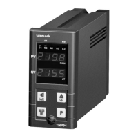
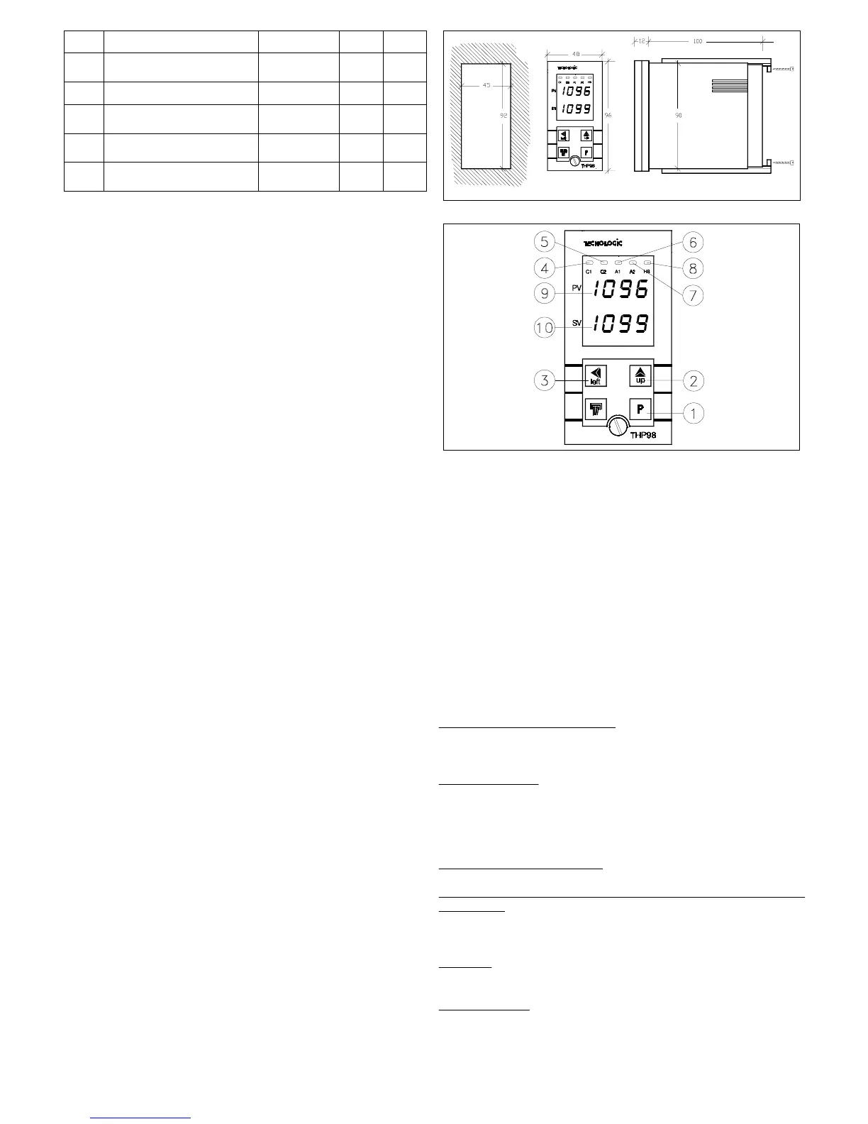
1.1 - FRONT PANEL
1 - Key P : Use to program the functioning parameters and to confirm the
programmed data and pass then to the next parameter.
2 - Key UP: Used to increase the figure on which is placed the "cursor".
(in case of parameters not numerical, "UP" key is needed to select the
available options)
3 - Key LEFT : Used to shift the "cursor" (flashing) on the figure that is
desired to modify, to visualise the current measured by TAHB input and to
reset the alarm latch.
4 - Led C1 : Signalize when the output C1 is on (on) or off (off)
5 - Led C2 : Signalize when the output C2 is on (on) or off (off)
6 - Led A1: Signalize when the output A1 is on (on) or off (off)
7 - Led A2: Signalize when the output A2 is on (on) or off (off)
8 - Led HB: Signalize when the output HB is on (on) or off (off)
9 - Display PV: Normally shows Process Value
10 - Display SV: Normally shows Set Point Value
1.2 - INSTRUMENT CODE
THP 98 T aa bb c d e ff
aa
= Heater Break Alarm Function
-- : Not present
HR : Present with Relay output (HB)
HO : Present with 24 VDC output for SSR driving (HB)
bb
= Alarm Outputs
-- : No Alarm
1R : 1 Alarm with Relay output (A1)
2R : 2 Alarms with Relay output (A1, A2)
1O : 1 Alarm with 24 VDC output for SSR driving (A1)
2O : 2 Alarms with 24 VDC output for SSR driving (A1, A2)
c =
Primary Control Output (C1)
R : Relay output and 24 VDC output for SSR driving
d =
Secondary Control Output for double action Pid control (Heating
and Cooling)
- : Not present
R : Relay Output
O : 24 VDC output for SSR driving
e =
Supply
L : 24 VAC/VDC
H : 90 ... 240 VAC
ff = Special
Codes
TECNOLOGIC - THP 98 USER MANUAL (I - GB) - Vr. 01 - ISTR 00372 - PAG. 7

 Loading...