16
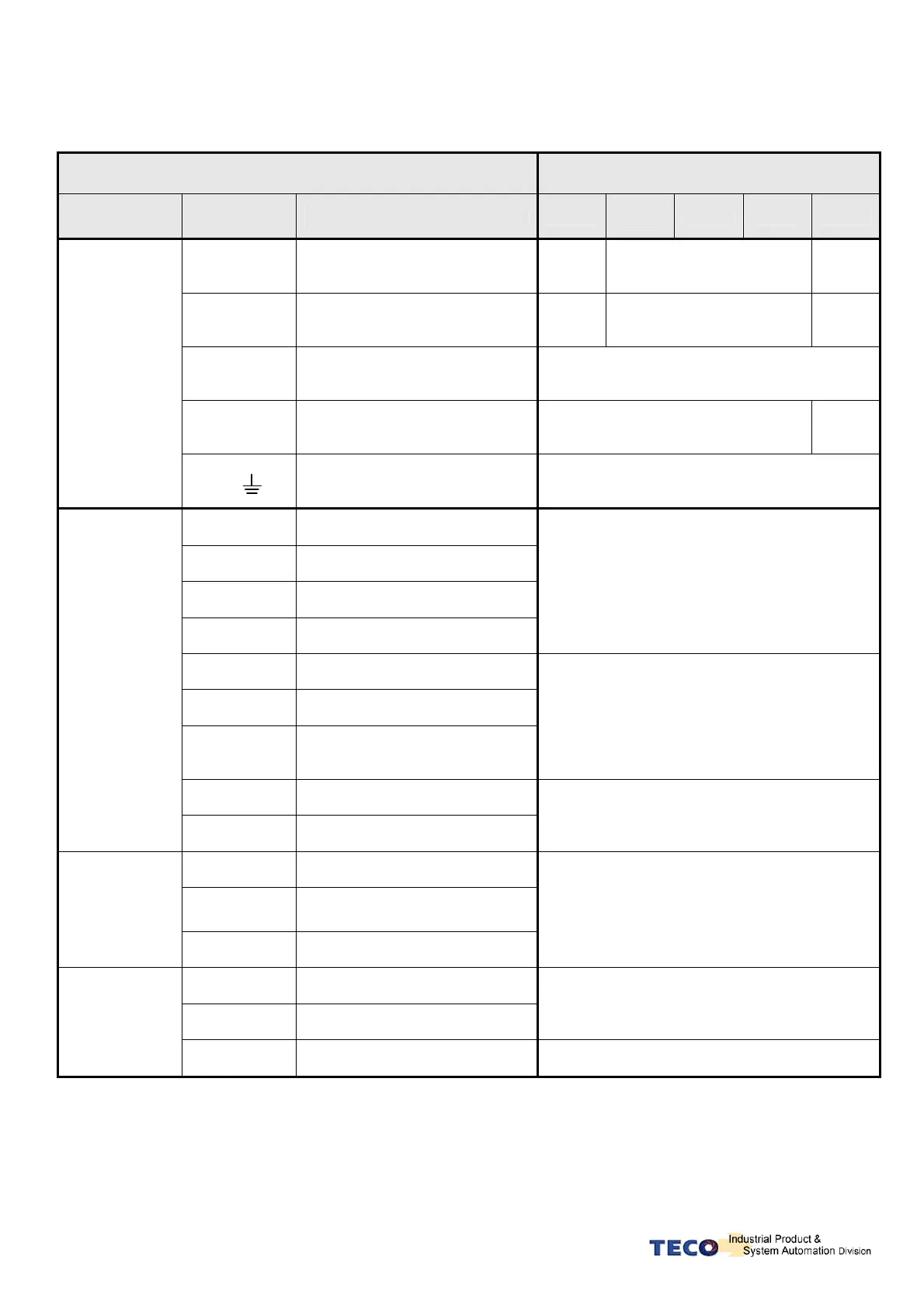
2-1-3 Specifications of Wiring
Connection Terminal
Servo Drives and Wire Specifications mm²
(AWG)
Connection
Terminal
Mark
(Sign)
Name of Connect Terminal
15 20 30 50 75
R, S, T
Main Power Terminal
1.25
(16)
2.0
(14)
3.5
U, V, W
Motor Terminal
1.25
(16)
2.0
(14)
3.5
(12)
R,s
Power-Control Terminal
1.25
(16)
P、Pc
External regeneration resistance
terminal
1.25
(16)
2.0
(14)
Terminal
1
FG
Ground Over 2.0(14)
26,27,28
Speed / Torque Command Input
30,31
Analog Monitor Output 1 & 2
33,34
Power Output +15V & -15V
29,32,44
Analog Ground Terminal
0.2mm ² or 0.3mm ² -> Twisted-pair-cable
connecting to the Analog Grounding wire
(including shield cable)
1~13,47
General Analog Input
18~25,43
General Analog Output
45,46,
48,49
24V Power &
I/O Ground
0.2mm ² or 0.3mm ² -> Twisted-pair-cable
connecting to the I/O Grounding wire (including
shield cable)
14~17,41
Position Command Input
CN1
Joint Control
Signal
35~40
Encoder Signal Output
0.2mm ² or 0.3mm ² -> Twisted-pair-cable
(including shield cable)
1,2
Output 5V
3,4
Output Grounding wire of power
supply
CN2
Joint of motor
encoder
5~18
Encoder Signal Input
0.2mm ² or 0.3mm ² -> Twisted-pair-cable
(including shield cable)
2,3
Data transfer & receive
5
Communication grounding wire
0.2mm ² or 0.3mm ² -> Twisted-pair-cable
(including shield cable)
CN3
CN4
Communication
connector
1,4,6,8
Floating
—
P.S.: 1. Please pay attention to the NFB and the capacity of noise filter when using multi-Drives.
2. CN1 ->25 Pins (D-SUB)
3. CN2 -> 9 Pins (D-SUB)
4. CN3/CN4-> 8 Pins Mini-Din type