25
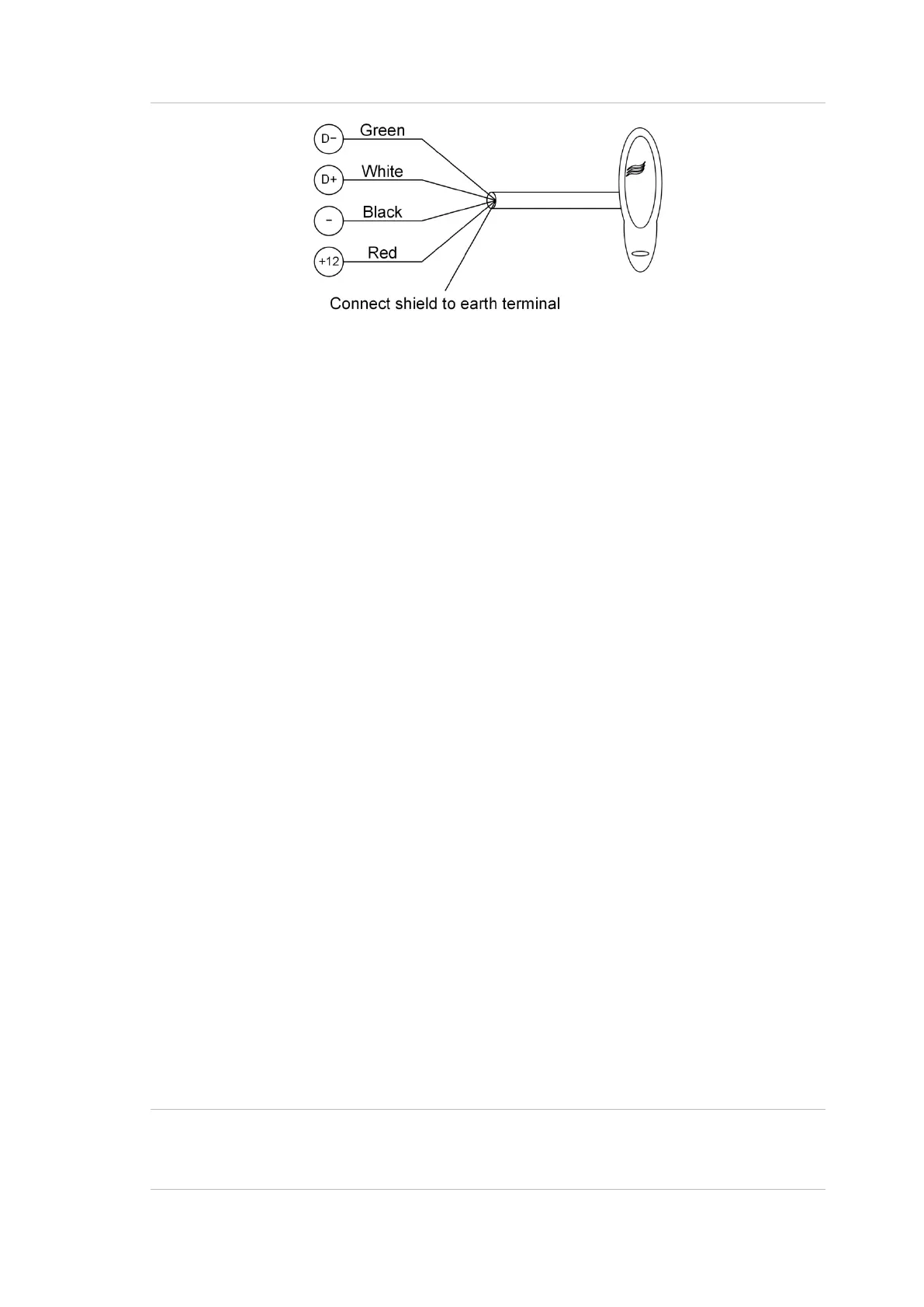
Figure 6: Connecting a Smart Card Reader to the one of the buses
Terminating the RS-485
All RS-485 devices (including the panel) use a 470 Ω RS-485 termination resistor
where required. RS-485 termination resistors are used to set the impedance of
the RS-485 to around 220 Ω in order to minimise noise. The termination resistor
may be external or on-board (devices with an on-board resistor use a link to set
the RS-485 termination to ON).
A RS-485 should have only two devices with the RS-485 termination set to ON
(or the RS-485 termination resistor fitted):
• In a straight RS-485 configuration, the TERM links are ON at the
ChallengerPlus panel and the most distant device.
• In a star RS-485 configuration, the TERM links are ON at the two devices
that are the furthest apart (and OFF at the ChallengerPlus panel).
In a completely connected (but powered down) system, you can check for correct
LAN termination by measuring the resistance across the D+ and D− terminals:
• 0 Ω indicates a short circuit in the cabling
• 160 Ω or less indicates that too many devices are terminated
• 220 Ω is good
• 470 Ω or more indicates that not enough devices are terminated
Lock power
There are two cable sockets providing extra lock power (Figure 2 on page 13,
items 21 and 31), if required. The sockets are for easy connection to Tecom
peripheral that support the connection, such as the TS1061 Dual Wiegand
Interface.
Connect a 2-way lock power cable (supplied with the Tecom peripheral) to one of
the 2-pin plug-in lock power sockets.
Refer to Figure 4 on page 23 for example connections of 2-way lock power
cables from a Network Access Controller to a Tecom peripheral (items A and C).
Note: Devices connected to the RS-485 buses and powered by the Network
Access Controller must comply with Appendix B: Output fusing and user current
limits on page 34


 To Next Page