26
Door lock relay wiring
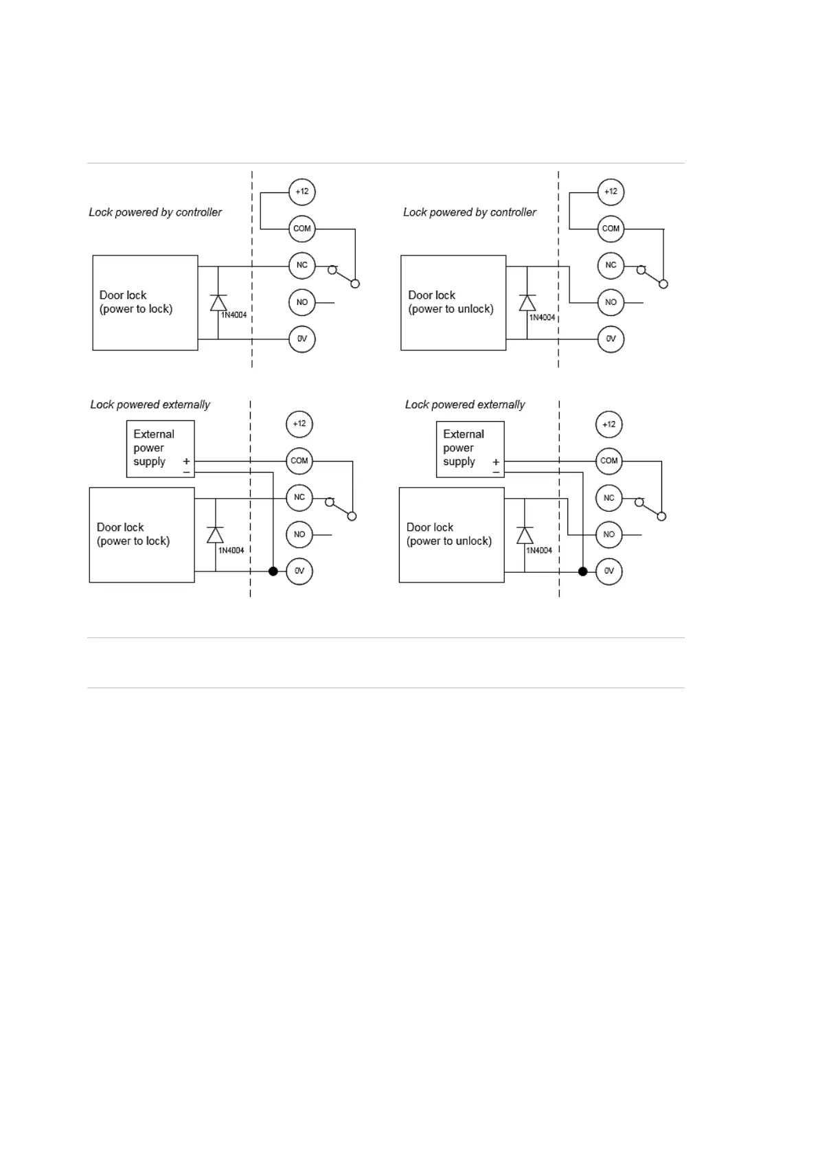
Figure 7 below details the wiring for the relay terminal blocks.
Figure 7:
Note: A suppression diode such as 1N4004 must be used in door lock circuits.
The diode must be co-located with the lock.
When using on board 12V power for locks, refer to Appendix B: Output fusing
and user current limits on page 34.
When powering locks from an external power supply or using the relays for other
purposes, the relay contact rating must be observed.
Maximum switching capacity (resistive/load):3A, 30VDC.
Minimum switching capacity: 100mA, 5VDC
Inputs
Inputs can be configured as an alarm input if the Network Access Controller is
connected to a ChallengerPlus system via the LAN.
A Challenger system can receive alarm signals from:
• The Challenger panel’s on-board inputs
• Inputs connected to Data Gathering Panels (DGPs)
Each pair of input terminals may be connected to a device such as a detector or
reed switch.