28
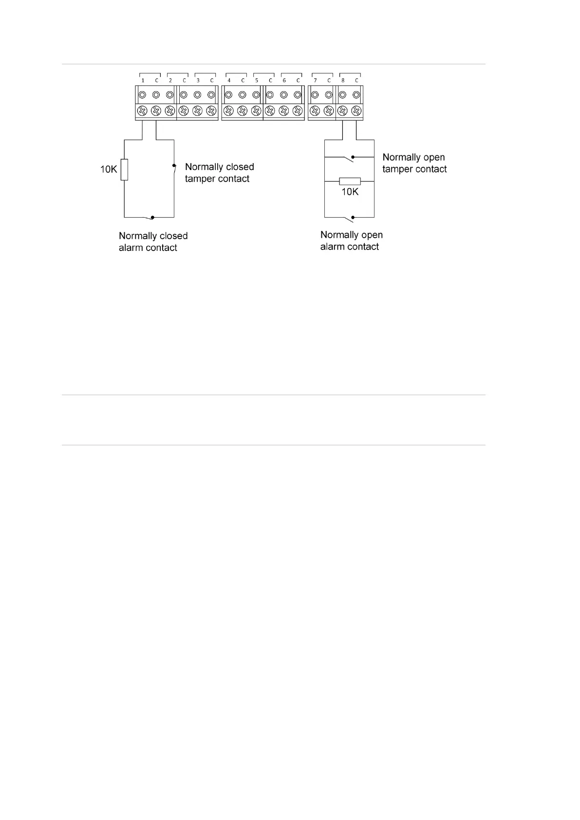
Figure 9: Two-state monitored input circuits
The panel uses the circuit’s resistance to determine the state of the input. In this
example, 10 kΩ EOL resistors have been used:
• 10 kΩ indicates sealed
• Open circuit or short circuit indicates unsealed
To use two-state monitoring, tamper monitoring must be disabled for the Network
Access Controller. See the TS1066 Network Access Controller Programming
Manual for information on disabling tamper monitoring.
Note: Two-state monitoring is not compatible with input types 33 or 40. See the
MAPROG-TS1066 R1.2 TS1066 Network Access Controller Programming
Manual for details.
Connecting expansion modules
Relay expansion
The Network Access Controller has four onboard relays that are assigned the
first four relay numbers.
If relay expansion cards are used, additional relays are numbered according to
their physical address, starting at 5. The Network Access Controller allows for
relay mapping to be programmed such that a physical relay number (e.g. 5) can
be mapped to a relay number in the ChallengerPlus system (e.g. 21).
One TS0840 Four-Way Relay Card may be connected to the Relay Card
(Figure 2 on page 13, item 12) to add four relays. Alternatively, TS0841
Eight-Way Clocked Relay Expansion Boards or TS0842 16-Way Clocked Open
Collector Expansion Boards may be connected to the Relay Card individually or
daisy-chained to add eight relays per card (for TS0841) or 16 open collector
outputs per card (for TS0842).