- SIGNAL
SHIELD
- EXCITATION
- SENSE
+ EXCITATION
+ SENSE
+SIGNAL
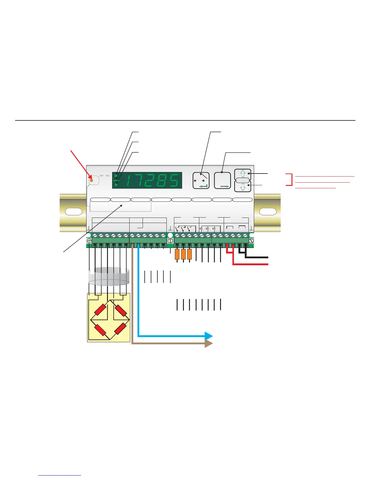
Load cell connections*
11-25
VDC
4-20mA
Output
Ground
RS422/485
Comms.
Recessed Enable Switch
(Enables changes to be made to important parameters.
Must be pressed AFTER entering ‘Set up’ mode but
before attempting to change parameters 1.1 to 1.3,
2.1 to 2.3 and 3.1 to 3.3)
Centre of Zero LED (±0.5d)
Minus Sign (>4 Digits ONLY)
Unit in Net Mode LED
Up Key
Down Key
Press either Key for more
than 3 seconds to enter
the ‘Set up’ Mode
Zero Key - Sets new zero (if enabled). Reverts to calibrated zero
if the button is held down for more than 3 seconds.
Switches unit back to ‘Gross’ mode if a tare has been set.
Acts as the ‘Enter’ key in the ‘Set-up’ Mode.
Tare Key - Puts unit into ‘Net’ mode. When inside
‘Set-up’ Menu this key moves the menu
back one step. Also moves ‘Digit Selected’
to the right when inside sub menus.
‘Set-up’ menu structure
0
Net
Digital Amplifier + Setpoint EZE30
+++ +
+
--- 0
0
Exc Sen Inp Inp Sen Exc
Load cell 5Vdc < 80mA
Isolated
Logic Outputs
Isolated
Logic Inputs
Isolated
Power 11 -25Vdc
++
--
Rx Rx Tx Tx
RS422/485
Gnd
0-20mA
Io
CL out
SET UP
1.Zero
1.0/allow>0<
2.Calibrate
3.Set mV/V
2.Span
1.Set cal ´n´
2.Calibrate
3.Set mV/V
4.Disp.mV/V
3.Display
1.o/u limits ´n´
2.
3.
4.Logic stats
Step*´n´
Dec.point
4.Filter
1.f Hz
2.Algorithm
3.Update rate
4.Motion´n´
cut
5.CLout
1.4mA=´n´
2.20mA=´n´
3.Base
4.Test I mA
6.Input 1/2/3
1.Assign Key
2.
3.
4.Test
7.Outp. 1/2/3
1.SPoint´n´
2.Hyst. ±´n´
3.Base
4.Test
8.Datacom.
1.Baud rate
2.422/485
3.Address
4.Auto trnsm.
T
T
T
0
T
12
3
4
1 2 3 com
1 2 3 com
depress
to
change
Logic input
Logic output
123
123
Logic Input 1 (+)
Logic Input 2 (+)
Logic Input 3 (+)
Logic Inputs (0V)
Logic Inputs
Receive +
Logic Outputs (0V)
Transmit +
Transmit -
Receive -
Logic Output 1 (+)
LOAD
Logic Output 2 (+)
LOAD
Logic Output 3 (+)
LOAD
*Please note that if you have a 4
wire cable from your junction box
or load cell to the EZE30, you
MUST put in additional links
between the Exc+ and Sen+
terminals and between the Exc-
and Sen- terminals. Otherwise the
display will show Err 5 (faulty load
cell connection)
Page 3