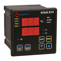
EasyManuals Logo

TECSYSTEM NT935 ETH User Manual

TECSYSTEM NT935 ETH
33 pages
To Next Page IconTo Next Page
To Previous Page IconTo Previous Page
Page #11 background imageLoading...
Page #11 background image
11
NT935 ETH
NT935 ETH
1)
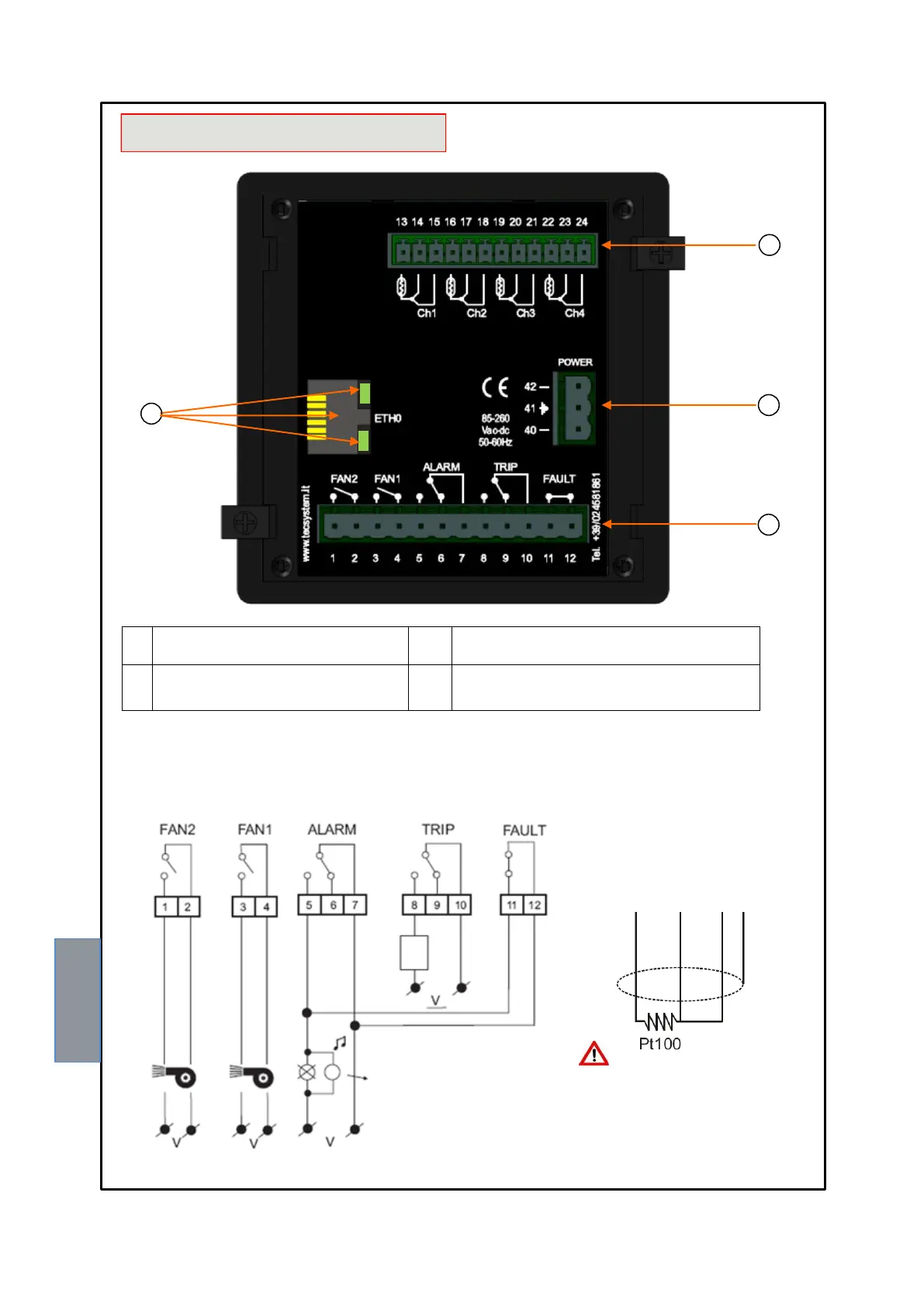
Pt100 sensors (white-red-red)
3)
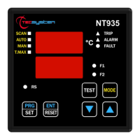
Relays (FAN2-FAN1-ALARM-TRIP-FAULT)
2)
Supply 85-260Vac-dc 50/60Hz.
4)
RJ45 Ethernet output, Link-Activity LED, see
indication on page 30.
SCREEN
RED
RED
WHITE
ELECTRICAL CONNECTIONS
1
2
3
4
1MN0095 REV. 0
Output relay with 10A-250Vac-res COSФ=1 contacts.
COSФ=1.
STOP
SYSTEM
ALARM
CONDITION AUDIO AND
VISUAL INDICATION
Pt100 CONNECTION EXAMPLE
Note: before connecting the
sensors to the control unit, read
the Measurement signal transfer
paragraph on page 15.
Note: relay contact image in non-alarm condition, with the exception of the FAULT relay that opens: contact 11-12
open (NO) contacts 11-12 closed (NC) fault condition identification. Read the Alarms and Ventilation paragraph on
page 12 and see the opening of the fault contact.
RELAY CONNECTION EXAMPLE

Questions and Answers:

Question and Answer IconNeed help?

Do you have a question about the TECSYSTEM NT935 ETH and is the answer not in the manual?

TECSYSTEM NT935 ETH Specifications

General IconGeneral
BrandTECSYSTEM
ModelNT935 ETH
CategoryController
LanguageEnglish

Related product manuals