EasyManuals Logo

TECSYSTEM t154 User Manual

TECSYSTEM t154
19 pages
To Next Page IconTo Next Page
To Previous Page IconTo Previous Page
Page #10 background imageLoading...
Page #10 background image
10
T154
T154
1
2
3
1MN0125 REV. 0
1)
Pt100 sensors (white-red-red)
3)
Relays (FAN1-ALARM-TRIP-FAULT)
2)
Supply 24-240Vac-dc 50/60Hz.
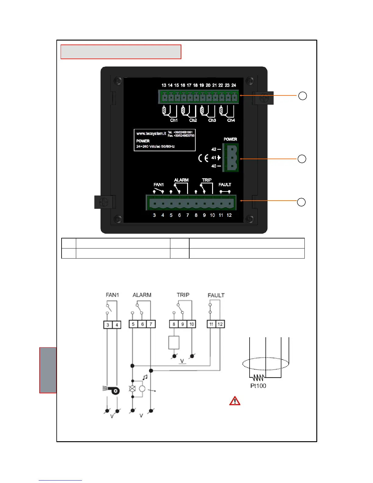
Note: relay contact image in non-alarm condition, with the exception of the FAULT relay that switches: contact 11-12 open
(NO), contacts 11-12 closed (NC) fault condition identification. Read the Alarms and Ventilation paragraph on page 11 and see
the fault contact switching.
RELAY CONNECTION EXAMPLE
Pt100 CONNECTION EXAMPLE
SYSTEM
STOP
ALARM AUDIO
AND VISUAL
INDICATION
Note: Before connecting the
sensors to the control unit, read
the Measurement signal transfer
paragraph on page 14 carefully.
Output relay with 10A-250Vac-res COSФ=1 contacts
ELECTRICAL CONNECTIONS
WHITE
RED
RED
SCREEN

Other manuals for TECSYSTEM t154

Questions and Answers:

Question and Answer IconNeed help?

Do you have a question about the TECSYSTEM t154 and is the answer not in the manual?

TECSYSTEM t154 Specifications

General IconGeneral
BrandTECSYSTEM
Modelt154
CategoryComputer Hardware
LanguageEnglish

Related product manuals