MEASUREMENT SIGNAL TRANSFER
All the cables transferring the Pt100 measurement signals must comply with the following under all circumstances:
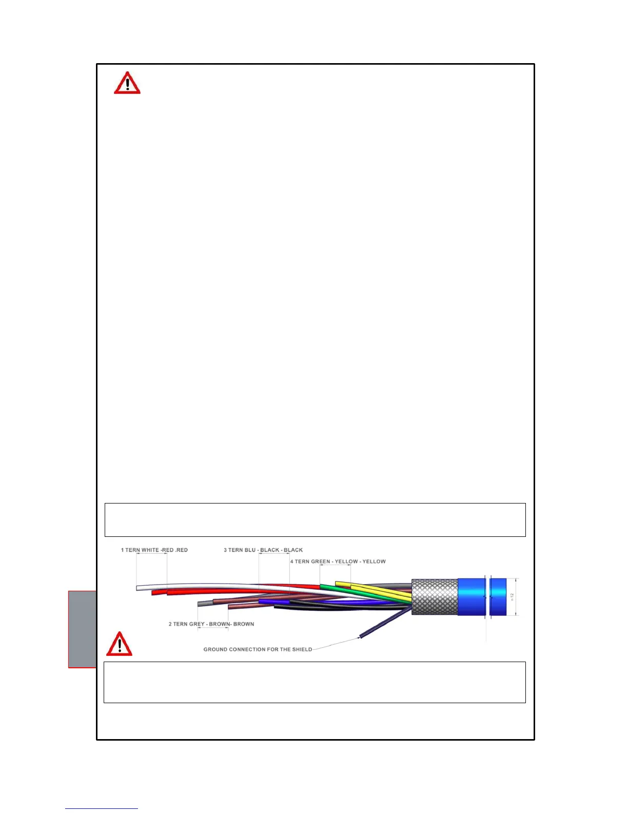
1. Every Pt100 must be connected with a three-wire cable having a minimum section of 0.35mm² and a maximum of 1 mm².
2. The extension cable must be screened with a tinned copper braid with 80% cover.
3. Conductors must be twisted, maximum recommended step 60mm.
4. The cable screening must be grounded only with a termination, preferably on the unit side.
5. The sensors' signal transfer cable must not be near any electrical cables, either low or medium-high voltage.
6. The Pt100 cable and the signal transfer cable must be laid in a straight line, without any winding.
7. Any caps used to butt conductors must be crimped properly to avoid false contacts.
NOTE: to install the sensors and signal transferring cable correctly, read the SCS / SENSOR installation
rules manual.
What may happen when installation rules are not complied with.
1) The electrical field propagating from the power line of another circuit, couples capacitively with the conductors
(in particular with unscreened cables). The effect of this coupling creates a signal that overlaps the signal transmitted
by the nearby conductors, causing incorrect readings.
2) The variations in magnetic flux in the power lines may induce an electromotive force on the signal transferring
cables (in particular non-twisted cables), that, being a closed circuit, generates a current. This interference current,
multiplied by the circuit resistance, gives a voltage value that overlaps the signal to be transmitted, distorting the sensor
measurement.
3) False contacts can alter the signal with the consequent variation in the temperature detected.
In specific cases, when the rules for connecting the Pt100 sensors are not complied with, the following anomalies can
occur between the SCS box and the temperature control unit:
a) incorrect temperature readings, alarms or anomalous tripping
b) mechanical / electrical fault of the Pt100 sensors
c) damage to the Pt100 inputs of the control unit.
TEMPERATURE SENSORS
Each Pt100 thermometric sensor has one white and two red wires (CEI 75.8 regulations).
The CH2 channel must be always referred to the central column of the transformer.
The CH4 channel must be always referred either to the core of the transformer or to the Pt100 ambient sensor ,if you
wish to thermo-regulate the transformer room using the T154 control unit.
We recommend you check the unit's programming before starting the device.
The default parameters set by TECSYSTEM might not match your requirements.
Programming the device is the end user's responsibility, the settings of the alarm thresholds and the enabling
of the functions described in this manual must be checked (by a specialized engineer) according to
the application and features of the system where the control unit i is inst