17
potential relay removes the start ca-
pacitor from the circuit after the mo-
tor is up to speed. This motor may
use either:
•anexternalthermalprotector,or
•aninternalthermalprotector.
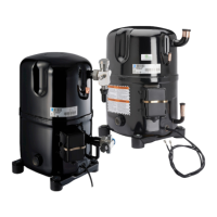
Permanent Split Capacitor
(PSC)
Here a run capacitor is in series with
the start winding. Both run capacitor
and start winding remain in the circuit
during start and after motor is up to
speed (see Figure 3-5). This normal
starting torque motor is sufficient for
capillary and other self-equalizing
system. No start capacitor or relay
is necessary. For additional starting
torque, a proper start assist kit may
be added (see Figure 3-6). Some
start assist kits may include:
•awired-inPositiveTemperature
Coefficient (PTC) relay, or
•amodulePositiveTemperature
Coefficient (PTC) relay.
This motor may use either:
•anexternalthermalprotector,or
•aninternalthermalprotector.
PSC motors are basically air condi-
tioning compressor motors and are
very common up through 5 HP.
PSC Motor Starting
Tecumseh Products Company pioneered the
development of Permanent Split Capacitor
compressor motors. This type of motor elim-
inates the need for potentially troublesome
and costly extra electrical components, e.g.,
start capacitors and potential motor starting
relays (see Figure 3-5).
To fully realize the capabilities of this simplified
type of compressor motor, it is necessary
to understand its starting and operating
characteristics and the field conditions that
can affect it.
The following conditions affect PSC motor
starting:
• Lowvoltage: Reduces motor start-
ing and running torque. A 10%
voltage drop reduces a motor’s
starting ability by 19%. Low volt-
age can cause no start, hard start,
light flicker, and TV screen flip flop.
PSC motor diagram with start
assist kit that includes a module
PTC relay
FIGURE 3-6:
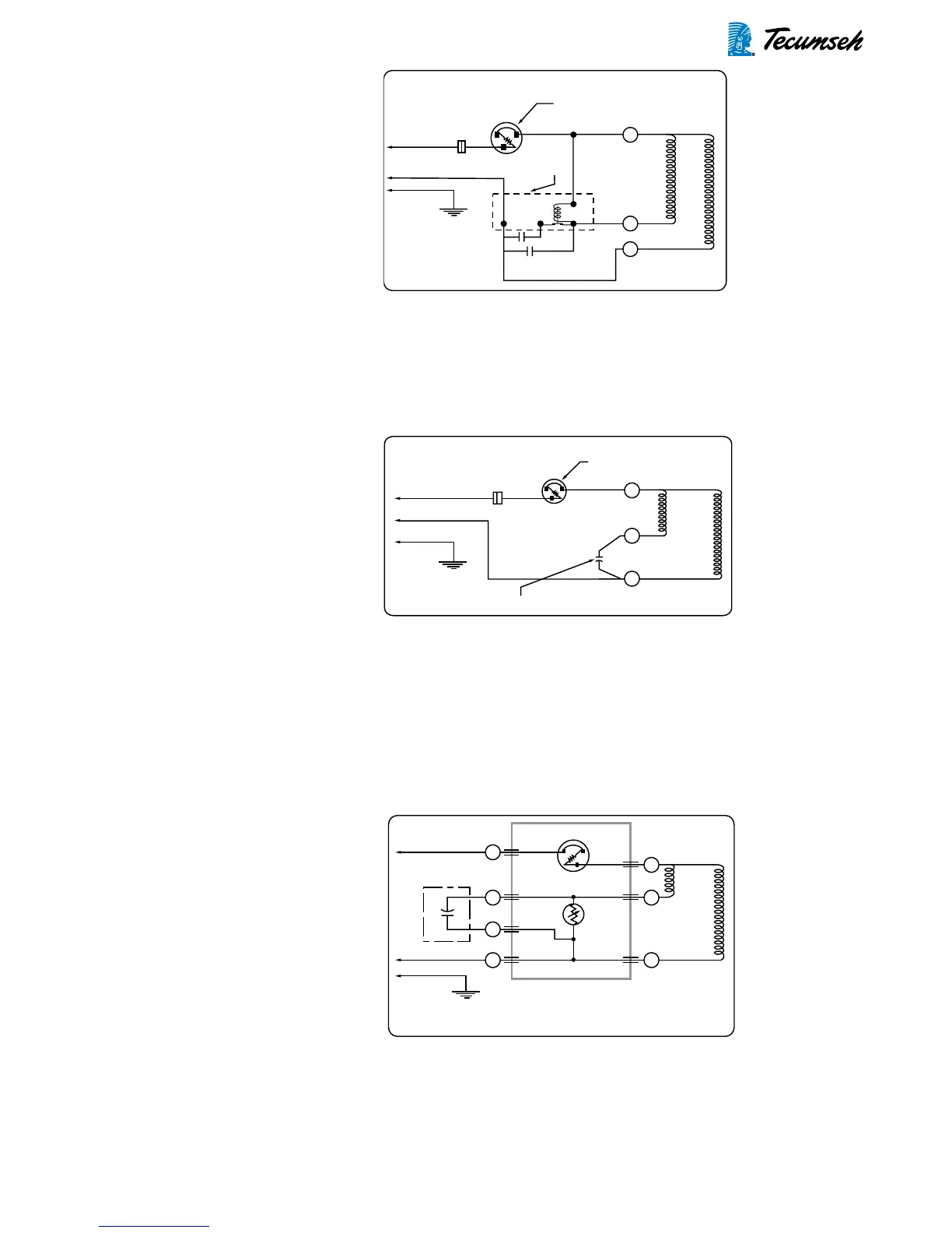
CSR motor diagram
FIGURE 3-4:
PSC motor diagram
FIGURE 3-5:
Relay -
Potential
Compressor -
Unit Ground
Line 1
Line 2
Ground
Start Winding
Main Winding
Control
External or Internal
Thermal Protector
C
S
R
Compressor -
Unit Ground
External or Internal
Thermal Protector
Run Capacitor
Line 1
Line 2
Ground
Start Winding
Main Winding
Control
C
S
R
Line 1
Line 2
Ground
Compressor -
Unit Ground
PTC
Relay
Plug-In
Run Capacitor
PTC Starting and
Protector Package
Thermal Protector
Start Winding
Main Winding
C
C
C
2
C
1
N
S
R
(115
Volt Only - Neutral)
(115
Volt Only - Neutral)