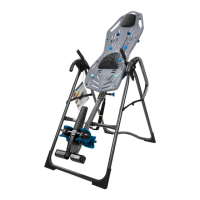
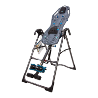
STEP ONE
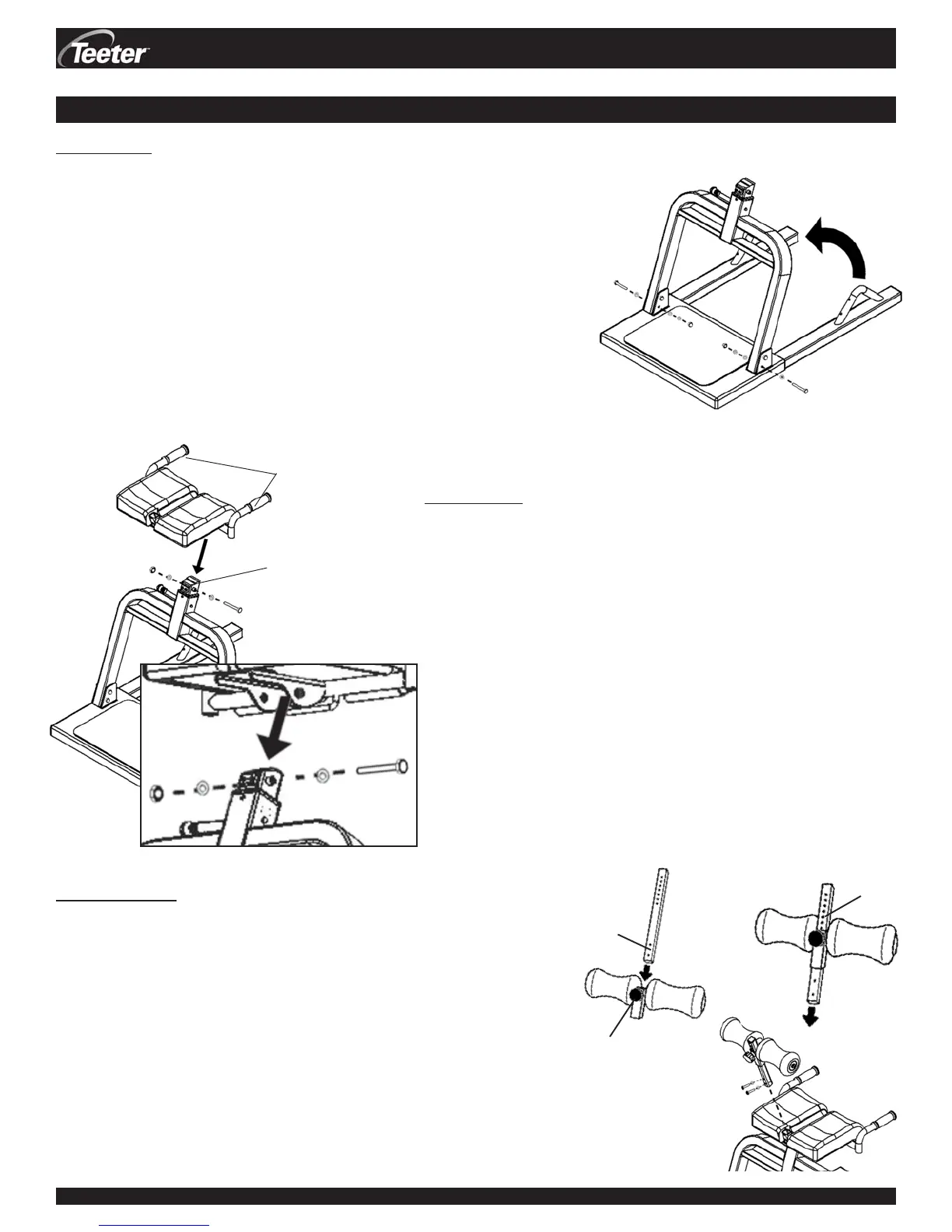
Position the Support Post (D1-1003) on the Base Frame (D1-1002)
• The Base Frame and Support Post arrive pre-assembled in the storage
position. Remove only the LOWER Hex Bolt from each column of the
Support Post. Keep this hardware nearby.
• Rotate the Support Post up approximately 80 degrees until the two
lower holes in the Support Post align with the lower holes in the Base
Frame (See Figure 1).
• Insert the Hex Bolt with Flat Washer from the outside through the
lower holes in each column. Finish with another Flat Washer and a
Lock Washer and fasten with the Capped Nut using a 9/16” Wrench.
Figure 1
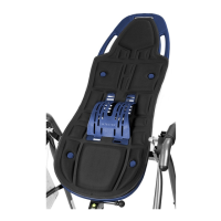
STEP TWO
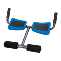
Secure the Lap Pad Assembly (D1-1004) to the Chrome Shaft in
the Support Post (D1-1003)
• Remove the Hex Nut, Flat Washers and Hex Bolt from the
Lap Pad Assembly (leave the bushings in place). Keep this
hardware nearby.
• With the Traction Handles facing the rear of the Support Post,
place the Lap Pad Assembly over the Chrome Shaft and align
the holes (See Figure 2).
• Thread the Hex Bolt through a Flat Washer. Insert through the
holes, securing the Lap Pad Assembly to the Chrome Shaft.
Finish with the remaining Flat Washer and Hex Nut. Secure
using a 9/16” Wrench. (See Figure 2A for close-up view)
• Make sure the fasteners are securely tightened and the Lap
Pad rotates smoothly.
DEX
TM
Assembly Instructions #LD-1001 Pg. 2
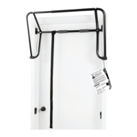
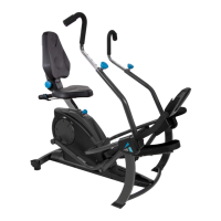
STEP THREE
Attach the Leg Roller Assembly (D1-1007) to the Lap Pad
Assembly (D1-1004)
• You must remove the Hex Bolts and Flat Washers from the Leg
Roller Assembly before proceeding. Keep this hardware nearby!
• Loosen the Adjustment Knob and slide the bottom of the Leg
Roller Shaft into the Leg Roller Adjustment Frame (See Figure
3A). Align to any one of the adjustment settings and secure by
hand-tightening the Adjustment Knob (See Figure 3B). Do not
overtighten.
• Slide the Leg Support Shaft into the receiving end of the Lap Pad
Assembly (See Figure 3C). Lining up the two holes, re-insert the
Flat Washers and Hex Bolts. Secure using a 13 mm Wrench.
ASSEMBLY INSTRUCTIONS
ASSEMBLY
Figure 3C
Figure 3A
bottom
of shaft
Figure 3B
Adjustment
Settings
Adjustment
Knob
Figure 2
Figure 2A
Chrome
Shaft
Traction
Handles
(Rear)
(Front)