STEP 1
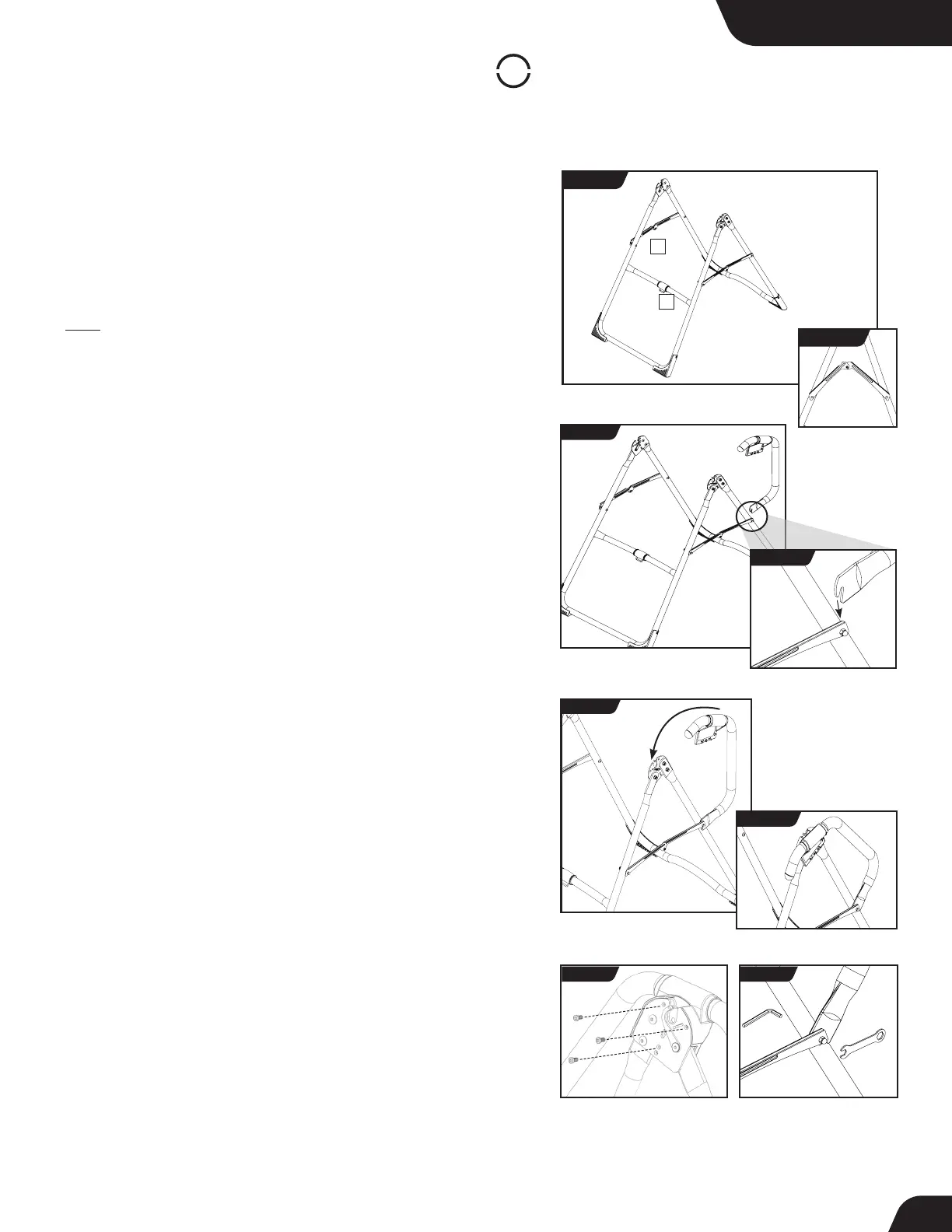
Assemble A-Frame Base & Stretch Max Handles
(X2 or X3 Models)
• On a level surface, position the A-Frame so that it is standing upright
and the Stability Feet are on the ground.
• Gently push down on the Spreader Arms to ensure they are fully open
and in the “locked” position (Figure 4).
• Look for temporary circular assembly assistance labels on the
A-Frame. RIGHT, LEFT, FRONT, and REAR indicate your position while
using the equipment, not facing it. These labels can be removed easily
upon completion of assembly.
• Locate the Handle Assembly Hardware Kit (HK1008).
• Determine the left or right handles, marked with an embossed L / R
on the inside of the black plastic part of each handle.
• Position the lower handle portion of the corresponding handle
(left / right) at the rear junction of the A-frame leg and Spreader
Arm (Figure 5 & 5a). The Lower Handle Bolt with Spacer has been
assembled loosely so that you will be able to seat the U-shaped
portion of the lower handle over the Spacer in between the
Spreader Arm and the A-frame leg. Do not tighten the bolt yet.
• Keeping the lower handle portion seated onto the Spacer, align the
upper handle portion’s black plastic part over the outside edge of the
Hinge Plate on the A-Frame (Figure 6 & 6a).
• Insert and loosely hand-tighten three of the Allen Head Screws
through the Hinge Plate into the handle (Figure 7).
• Now tighten the Lower Handle Bolt using the 5mm Allen Wrench
and Open Wrench provided, ensuring that it is fully secured but not
over-tightened (Figure 8).
• Finally, tighten the Allen Head Screws for the upper handle using
the 5mm Allen Wrench provided.
• Repeat these steps on the other handle.
FIGURE 5a
For X2 & X3 Models
FIGURE 5
FIGURE 6
FIGURE 6a
FIGURE 7 FIGURE 8
1 - Spreader Arms 2 - Crossbar
LEFT
RIGHT
FIGURE 4
1
2
REAR
FRONT
LOCKED
FIGURE 4a
UNLOCKED
7