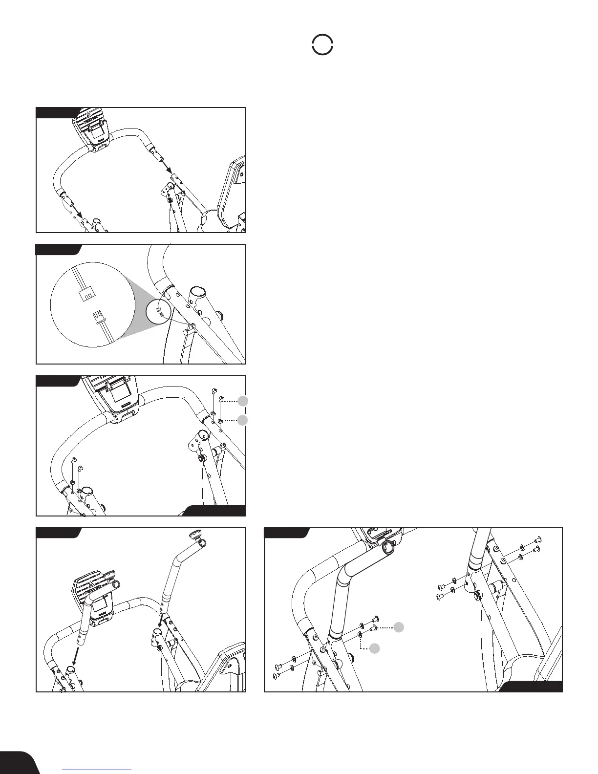
FIGURE 12
STEP
4
Assemble Supports
Console Front Support Bar Installation
IMPORTANT: Do not pull or pinch the Speed Sensor Wire during
the Console Front Support Bar Installation.
• Locate the Batteries (AA 1.5 V Alkaline) and install them in the
back of the Console in the Battery Compartment, noting
(+) and (-) symbols.
• Ensure that the Speed Sensor Wires remain on the outside. Align
both ends of the Console Front Support Bar with the Lower
Console Support Tube and insert (Figure 12).
• Carefully connect the Speed Sensor Wires (Figure 13).
• Use the Step 4a Hardware Kit to attach the Console Front
Support Bar. Hand tighten 4 × Bolts with 4 × Curved Washers as
shown. The Curved Washers should wrap around the shape of
the Lower Console Support Tube. Proceed to fully tighten the
Bolts with the Allen Wrench (Figure 14).
Handle Support Tube Installation
• Locate the Handle Support Tubes, noting Right and Left
markings. Insert the bottom of each Handle Support Tube into
the top of the Upper Pedal Arm (Figure 15).
• Use the Step 4b Hardware Kit to attach the Handle Support
Tubes. Hand tighten 8 × Bolts with 8 × Curved Washers as shown.
The Curved Washers should wrap around the shape of the Upper
Pedal Arms. Proceed to fully tighten the Bolts with the Allen
Wrench (Figure 16).
FIGURE 13
FIGURE 14
FIGURE 15 FIGURE 16
10 8
Bolt
10 9
Curved Washer
10 8
Bolt
10 9
Curved Washer
Step 4a Hardware
Step 4b Hardware
9