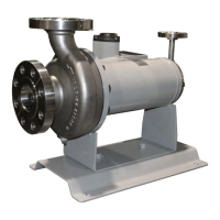
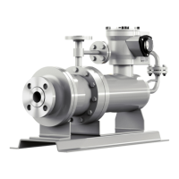
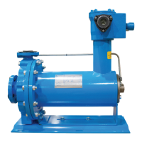
The Teikoku Type-R (Plan 13-SE) is a sealless canned motor pump specifically engineered for the industrial refrigeration market. It combines a centrifugal pump and a squirrel cage induction electric motor into a single, hermetically-sealed unit, offering an advanced low-probability, true secondary containment solution. This design provides an environmentally friendly alternative to traditional sealed pumps and single containment sealless pumps.
Function Description:
The primary function of the Teikoku Type-R pump is to circulate liquid within refrigeration systems. Its unique design ensures that the motor rotor and stator windings are completely isolated from the pumped liquid. The pump impeller, of the closed type, is mounted on one end of the rotor shaft, extending into the pump casing. The rotor is submerged in the pumped liquid, and the stator winding is protected by a corrosion-resistant, non-magnetic alloy liner, which effectively "cans" the stator winding.
A key operational feature is its liquid film journal bearings, which are submerged in and lubricated by the process liquid itself. The pump has only one moving component: a combined rotor-impeller assembly driven by the induced magnetic field of the induction motor. A portion of the pumped liquid circulates through the rotor cavity to cool the motor and lubricate these bearings.
The Teikoku Type-R employs a reverse circulation design (Plan 13-SE). Circulating liquid is channeled into the motor section through holes in the front bearing housing. A portion lubricates the front liquid film journal bearing and returns to the rear of the impeller. The remaining circulating liquid passes over the rotor, cooling the motor, lubricates the rear liquid film journal bearing, and then exits the rear bearing housing, returning to the vapor space of the suction tank via a dedicated reverse circulation line. This design prevents the heated circulating liquid from returning directly to the pump suction, optimizing efficiency.
The pump also features an automatic thrust balance system, based on hydraulic principles. The pressure of the pumped liquid itself, operating in a balance chamber at the front and rear of the impeller, accomplishes this balance. Should a change in load shift the impeller's position away from the balanced condition, an equalizing change of hydraulic pressure in the balance chamber immediately returns the impeller-rotor assembly to its balanced position.
A standard feature of the Teikoku Type-R (Plan 13-SE) is the patented Teikoku Rotary Guardian (TRG™), an electrical meter that continuously monitors the condition of the bearings. The TRG operates on the principle of induced voltage, with two coils located 180° apart inside the stator. A magnetic field is created by current flowing through the stator windings. When bearing wear occurs, and the gap between the rotor and stator decreases, an imbalance in the magnetic fields causes a differential induced voltage, which is indicated on the TRG voltmeter. This provides a direct readout of bearing condition, allowing for proactive maintenance.
Usage Features:
The Teikoku Type-R pump is designed for ease of installation and operation. It is supplied with a fabricated steel base cradle, and its operation is unaffected by mounting or operating position, eliminating the need for costly alignment procedures. However, careful attention to piping is crucial. Suction and discharge piping must be properly supported and aligned to prevent strain on the pump casing. Burrs and sharp edges should be removed from flanges, and inside diameters of flanged joints must match properly. Pipe hangers or supports should be used at necessary intervals, and provisions for pipe expansion should be made if required by liquid temperature. Welding joints while connected to the pump is strictly prohibited.
For optimal performance, the pump should be located as close as possible to the liquid supply with a positive suction head, ensuring sufficient Net Positive Suction Head (NPSH) over the vapor pressure of the liquid at the pump inlet. Suction piping should be short, direct, and never smaller in diameter than the pump's suction opening, ideally one or two sizes larger depending on length. Eccentric reducers with the flat side on top should be used to avoid air pockets.
Before initial start-up, it is essential to ensure that suction and discharge piping are free of foreign matter. The pump must be fully primed, vented, and liquid-full. Rapid temperature changes should be avoided to prevent leaks in gaskets. The TRG meter should be checked, and if it indicates a "RED" condition, the pump should not be operated, as this voids the warranty.
The pump's rotation direction must be verified, either using the TRG meter (Type-M AM-45), a hand-held TRC-1 indicator, or by monitoring pressure and amperage. If rotation is incorrect, any two electrical supply leads must be swapped. The thermal overload protective device in the motor starter should be set at the rated current indicated on the nameplate, or at 1.1 to 1.25 times the operating current, depending on voltage and load stability. It is crucial not to set this device higher than the full load amps (FLA) listed on the name tag.
During operation, the TRG meter should be checked periodically, and its readings recorded to track bearing wear. Discharge pressure should be stable, and motor amps should be within the expected range. The pump should never operate above its rated full load amps. If abnormal noise or vibration occurs, the pump should be stopped immediately, and the cause investigated.
For shutdown, the discharge valve should be closed, followed by stopping the pump. If the pump is to be removed from service or shut down for an extended period, reverse circulation, bypass, and suction valves should be closed, and the entire pump and connected piping drained, especially if there is a danger of freezing.
Maintenance Features:
The Teikoku Type-R pump is designed for maintainability, with replaceable components such as shaft sleeves, thrust collars, and liquid film journal bearings. Disassembly and reassembly procedures are detailed, requiring specific tools like metric socket wrenches, hex wrenches, dial indicators, dial calipers, feeler gauges, torque wrenches, and channel-lock pliers.
Prior to any disassembly, strict adherence to end-user-specific lockout/tagout procedures is mandatory. Power cables must be disconnected, and the pump drained according to user procedures. It is critical to always assume residual liquid may be present in the pump and motor, even after thorough decontamination.
During disassembly, the casing bolts are removed, and the casing is carefully slid off, taking care not to damage the impeller or inducer, or spill any remaining liquid. End play and "g" gap measurements should be recorded before further disassembly. The impeller bolt, lock washer, impeller, and inducer are then removed from the rotor shaft, followed by the impeller key.
The front and rear bearing housings are removed, exercising caution due to potential liquid containment. Impeller adjusting washers are also removed, noting their quantity and thickness. The rotor assembly is then removed and placed on a clean cloth to prevent damage. Front and rear shaft sleeves and thrust collars are removed, along with their anti-rotation pins/keys. Bearings are removed by unscrewing the set screw and sliding them out.
Inspection during maintenance includes checking thrust faces for scratches and chips, and the bearing bore for wear. Shaft sleeves and thrust surfaces are visually inspected for general appearance, uniform wear, undercutting, pitting, or scoring, which would necessitate replacement. The complete rotor assembly is inspected for cracks, breaks, pitting, or corrosion, and for shaft straightness. The stator assembly is inspected for cracks, breaks, pitting, or corrosion of the stator liner, and the electrical junction box for corrosion and moisture. A megger and resistance check on the motor winding are recommended. All mating faces must be free of nicks and burrs to ensure a good seal.
Reassembly involves cleaning and drying all parts. Adjusting washers are installed in the rear bearing housing to achieve proper rotor end play. Bearings are inserted with flat washers, aligning them with the set screw hole, and the set screw is tightened without overtightening. Anti-rotation pins/keys are installed, followed by the rear thrust collar and shaft sleeve, ensuring correct orientation and engagement. The lock bolt, flat washer, and lock washer are installed and torqued, with lock washer tabs bent over.
The assembled rotor is slid into the stator, followed by the rear stator gasket and rear bearing housing, tightening bolts evenly in a star or cross pattern. The front bearing housing is then slid onto the rotor and into the stator, ensuring the shaft sleeve is tight against the thrust collar and engaged. The rotating assembly must rotate freely without binding or rubs. Adjusting washers are installed on the rotor shaft for proper "g" gap. The impeller key, impeller, and inducer are installed, and the impeller bolt, flat washer, and lock washer are secured. Rotor assembly end play and "g" gap are checked and adjusted with washers as needed. The impeller bolt is tightened, and lock washer tabs are bent over. The assembled pump should rotate freely by hand without metal-to-metal contact.
Finally, the pump casing gasket is installed, and the casing is slid back onto the pump, tightening all bolts and adding new Teflon tape to plugs where needed. Teikoku USA recommends having a complete repair kit on hand for each pump model, including bearings, sleeves, thrust collars, gaskets, and lock washers. When ordering spare parts, the serial number, model number, part name, and impeller diameter (if applicable) should be provided.
For units returned for service, thorough decontamination is required to prevent corrosive attack during shipment or injury to personnel. A Decontamination Form must be completed, providing information on the fluid handled and operating conditions at the time of failure.