Teikoku USA | Chempump Instruction Manual HE-10677-P (1018)14
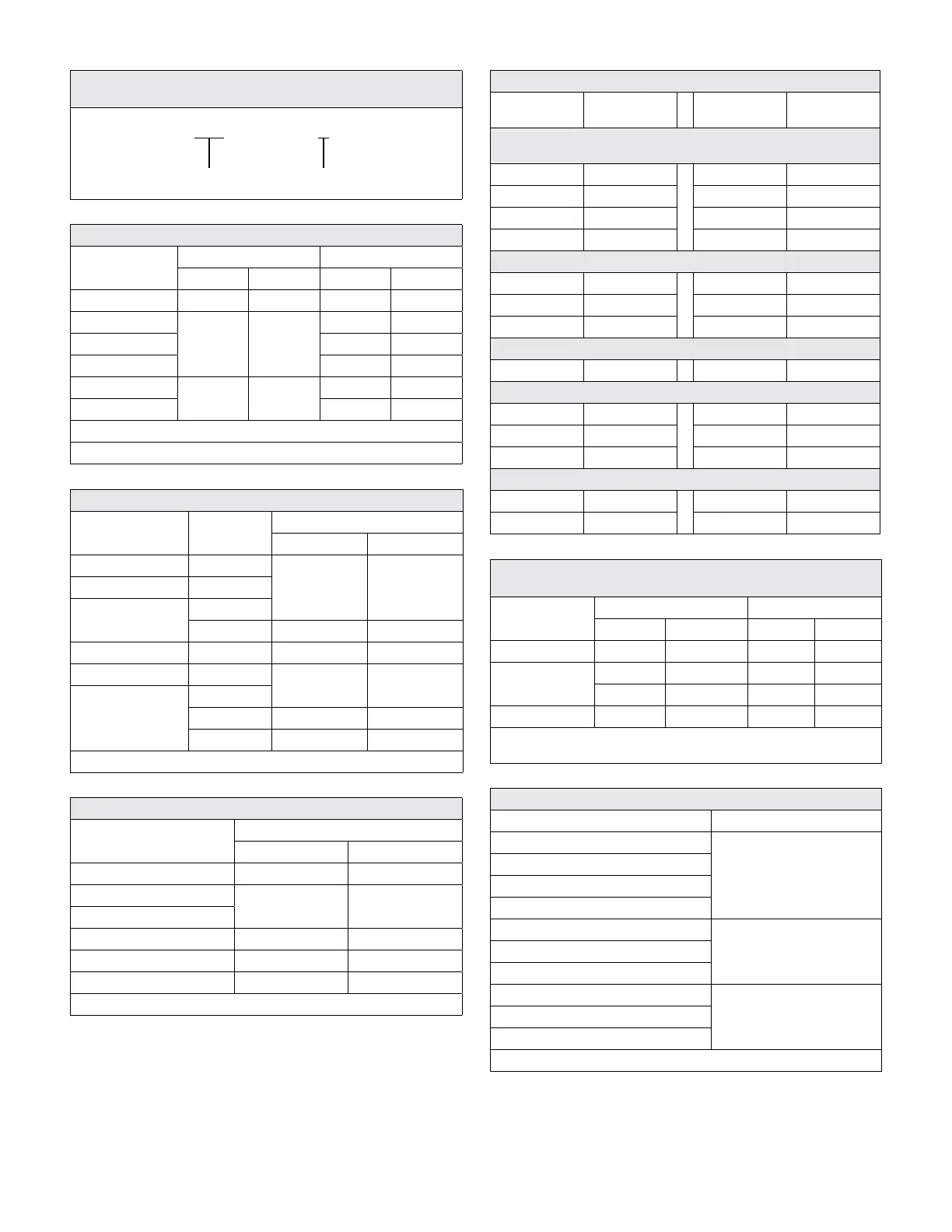
Figure 4-5. Type-R (Plan 13-SE) Model Number Indentification
Code Example
R42-316F4AM-0506T1-E
MOTOR FRAME IMPELLER SIZE
Table 4-1. Bearing Wear Limit
Motor
Frame Number*
øA – øB L
Inch mm Inch mm
119 0.012 0.3 1.746 44.2
215, 216, 217
0.016 0.4
1.937 49.2
316, 317 2.331 59.2
416, 417 2.724 69.2
426, 516, 518
0.020 0.5
3.079 78.2
526, 529 4.449 113
NOTE: For F, H, N, C, and U Insulations (Standard Carbon Bearings)
* See Figure 4-5
Table 4-2. Adjusting Value of Gap “g”
Motor
Frame Number*
Impeller
Size
“g” gap (rotor pulled)
Inch mm
119 R
.154 to .161 3.9 to 4.1215, 216, 217 S
316, 317
TS (S)
T .161 to .169 4.1 to 4.3
416, 417 T .173 to .181 4.4 to 4.6
426, 516, 518 U
.193 to .201 4.9 to 5.1
526, 529
U
V .232 to .240 5.9 to 6.1
W .248 to .256 6.3 to 6.5
* See Figure 4-5
Table 4-3. End Play
Motor Frame Number*
End-Play
Inch mm
119 .039 to .063 1.0 to 1.6
215, 216, 217
.043 to .067 1.1 to 1.7
316, 317
416, 417 .055 to .079 1.4 to 2.0
426, 516, 518 .067 to .091 1.7 to 2.3
526, 529 .071 to .094 1.8 to 2.4
* See Figure 4-5
Table 4-4. Tightening Torques
Bolt Size
Torque
(ft.lb.)
Bolt Size
Torque
(ft.lb.)
Rotor (304SS, 304LSS, 316SS, 316LSS)
Note: Rear rotor bolts have left-hand threads
M10 13 M18 73
M12 22 M20 109
M14 34 M22 145
M16 55 M24 181
Front Bearing Housing (304SS, 304LSS, 316SS, 316LSS)
M6 3.0 M12 22
M8 6.0 M14 34
M10 13 M16 55
Set Screw (316SS, 316LSS)
M6 1.3 M8 4.4
Pump Casing for Flat Gasket (304SS)
M6 3.0 M12 22
M8 6.0 M14 34
M10 13 M16 55
Pump Casing for Spiral Wound Gasket (SCM435)
M10 42 M14 116
M12 73 M16 181
Table 4-5. Torque Values for Motor Terminal Connections –
Terminal Box and Connection Stud Size
Terminal Box
Size*
Connection Stud Size** Torque Values
U, V, W X, Y, Z ft.lb Nm
Small (S) M6 — 2.9 4
Medium (M)
M8 — 7.4 10
M10 — 11 15
Large (L) M12 M12 21 29
* Refer to Table 4.6
** The number after the “M” represents the nominal threads OD (mm)
Table 4-6. Motor Frame and Terminal Box Size
Motor Frame Number* Terminal Box Size
118, 119
S
215, 216, 217
315, 316, 317, 325, 326
416, 425, 426
417
M515, 516, 517, 525, 526
625, 626
518, 615, 616, 617
L715, 716, 717, 718
725, 726, 727
* See Figure 4-5