23
Special requirements
before first use
Before connecting the hob to the electric
mains, check that the voltage and fre-
quency of the mains matches what is
shown on the hob’s rating plate, which is
located lower down, and on the guarantee
or, where appropriate, the technical datas-
heet supplied, which should be kept toge-
ther with this manual.
Touch control user
instructions
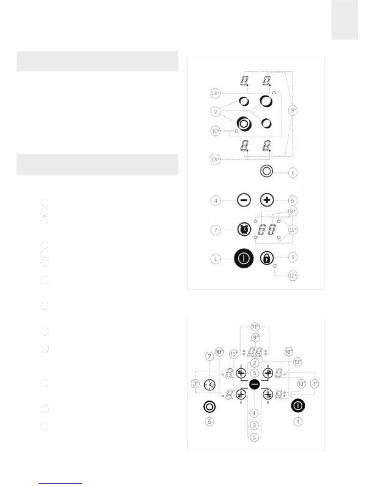
CONTROL COMPONENTS (figs. 7, 8 and 9)
On/off sensor.
Hotplate selection sensors.
Power and/or residual heat indicators
(also shows that blocking is activated on
models shown in figure 8).
Reduce power/time sensor (less).
Increase power/time sensor (more).
Select double circuit (double hotplate)
sensor.
Select timer/ counter sensor (models
VT TC 60 PH, TR 640, TT 640, TZ 640,
TC 620 and TR 735 AB).
Clock indicator (models VT TC 60 PH,
TR 640, TT 640, TZ 640, TC 620 and TR
735AB).
Blocking (the other sensors) sensor
(except on models shown in fig. 7 and 9).
Light indicating the hotplate's double
circuit is on (only adjacent to double cir-
cuit hotplates). On Triple circuit hotpla-
tes there is a second light.
Light indicating the hotplate clock is on
(models VT TC 60 PH, TR 640, TT 640,
TZ 640, TC 620 and TR 735 AB).
Blocking activated indicator light (on
models shown in fig. 7 and 9).
Decimal point on indicators:
Light on: Hotplate controllable.
Light off (switched off): Hotplate blocked.
* Only visible when in operation.
Use and Maintenance
fig. 7
1
2
3
4
5
6
7
8
9
10
11
12
13
Models VT TC 60.3 and VT TC 60 PH
fig. 8
Models TT 630, TT 600, TB 600,
TC 620, TR 600 and TR 735 AB