Operating Instructions—2213 Service
OPERATING CONSIDERATIONS
The following basic operating information and tech
niques should be considered before attempting any
measurements.
GRATICULE
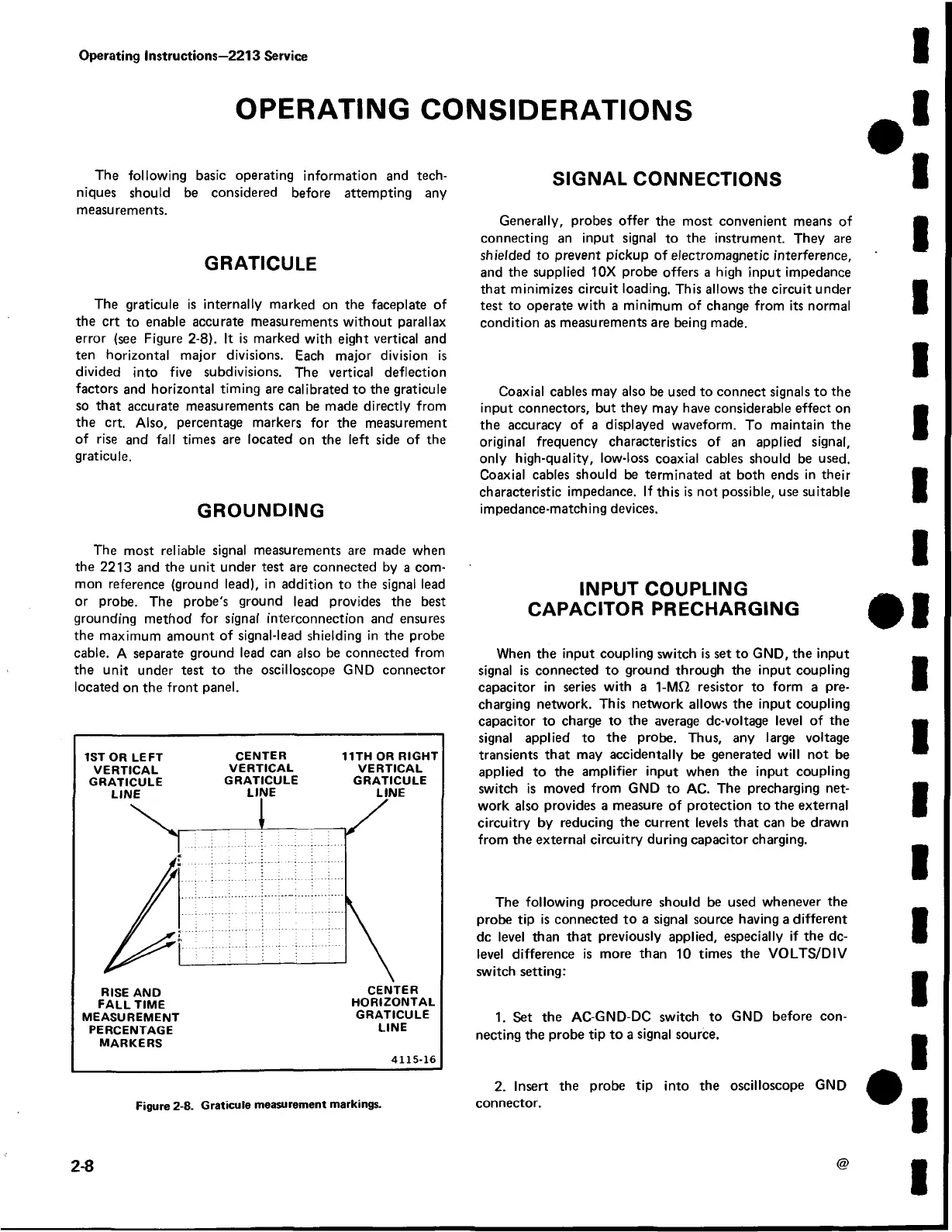
The graticule is internally marked on the faceplate of
the crt to enable accurate measurements without parallax
error (see Figure 2-8). It is marked with eight vertical and
ten horizontal major divisions. Each major division is
divided into five subdivisions. The vertical deflection
factors and horizontal timing are calibrated to the graticule
so that accurate measurements can be made directly from
the crt. Also, percentage markers for the measurement
of rise and fall times are located on the left side of the
graticule.
GROUNDING
The most reliable signal measurements are made when
the 2213 and the unit under test are connected by a com
mon reference (ground lead), in addition to the signal lead
or probe. The probe's ground lead provides the best
grounding method for signal interconnection and ensures
the maximum amount of signal-lead shielding in the probe
cable. A separate ground lead can also be connected from
the unit under test to the oscilloscope GND connector
located on the front panel.
1ST OR LEFT CENTER 11TH OR RIGHT
VERTICAL VERTICAL VERTICAL
GRATICULE GRATICULE GRATICULE
FALL TIME HORIZONTAL
MEASUREMENT GRATICULE
PERCENTAGE LINE
MARKERS
4115-16
Figure 2-8. Graticule measurement markings.
SIGNAL CONNECTIONS
Generally, probes offer the most convenient means of
connecting an input signal to the instrument. They are
shielded to prevent pickup of electromagnetic interference,
and the supplied 10X probe offers a high input impedance
that minimizes circuit loading. This allows the circuit under
test to operate with a minimum of change from its normal
condition as measurements are being made.
Coaxial cables may also be used to connect signals to the
input connectors, but they may have considerable effect on
the accuracy of a displayed waveform. To maintain the
original frequency characteristics of an applied signal,
only high-quality, low-loss coaxial cables should be used.
Coaxial cables should be terminated at both ends in their
characteristic impedance. If this is not possible, use suitable
impedance-matching devices.
INPUT COUPLING
CAPACITOR PRECHARGING
When the input coupling switch is set to GND, the input
signal is connected to ground through the input coupling
capacitor in series with a 1-MS2 resistor to form a pre
charging network. This network allows the input coupling
capacitor to charge to the average dc-voltage level of the
signal applied to the probe. Thus, any large voltage
transients that may accidentally be generated will not be
applied to the amplifier input when the input coupling
switch is moved from GND to AC. The precharging net
work also provides a measure of protection to the external
circuitry by reducing the current levels that can be drawn
from the external circuitry during capacitor charging.
The following procedure should be used whenever the
probe tip is connected to a signal source having a different
dc level than that previously applied, especially if the dc-
level difference is more than 10 times the VOLTS/DIV
switch setting:
1. Set the AC-GND-DC switch to GND before con
necting the probe tip to a signal source.
2. Insert the probe tip into the oscilloscope GND
connector.
2-8
@
 Loading...


