Theory of Operation—2213 Service
Capacitor C644 charges rapidly to the new voltage
difference through R642 to produce a very narrow pulse
output across R642. When the holdoff period ends, the
Q output of U640B goes HI again and C644 charges in the
opposite direction through VR644. The resulting A lt Sync
signal is applied to the Channel Switching circuit to syn
chronize the horizontal display with channel switching
transitions when using ALT VERTICAL MODE.
Delay Circuit
The Delay circuit, composed of Q624, Q632, Q644,
Q650, Q652, U607D, and associated components, generates
the timing and gate signals required to produce the inten
sified Sweep display and to provide the variable Sweep
delay. HORIZONTAL MODE switch S650 controls the
display mode (NO DLY, INTENS, or DLY'D), and DELAY
TIME switch S660 selects the basic delay time (0.2 ms,
10 ps, or 0.5 ms). The DELAY TIME MULTIPLIER
control (R658) increases the possible delay available by up
to at least twenty times the basic delay.
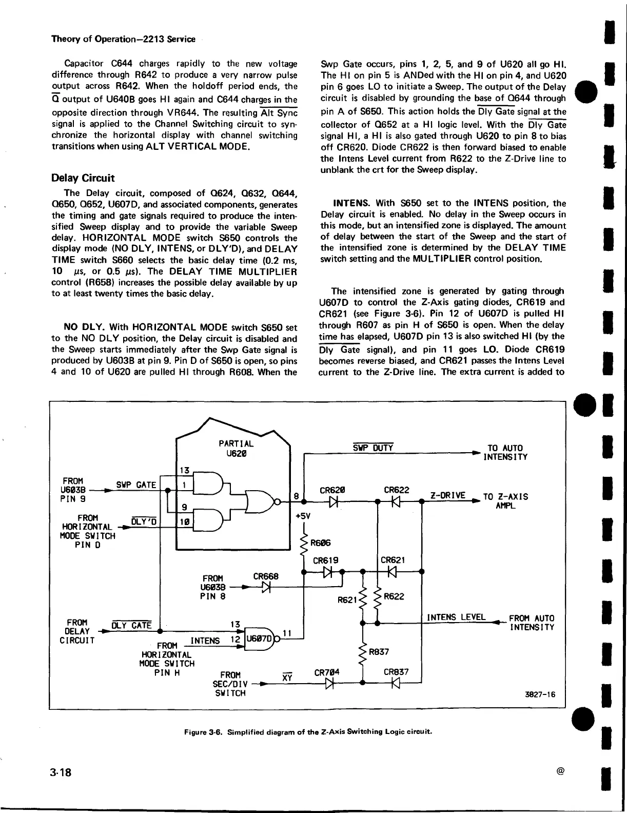
NO DLY. With HORIZONTAL MODE switch S650 set
to the NO DLY position, the Delay circuit is disabled and
the Sweep starts immediately after the Swp Gate signal is
produced by U603B at pin 9. Pin D o f S650 is open, so pins
4 and 10 of U620 are pulled HI through R608. When the
Swp Gate occurs, pins 1, 2, 5, and 9 of U620 all go HI.
The HI on pin 5 is ANDed with the HI on pin 4, and U620
pin 6 goes LO to initiate a Sweep. The output of the Delay
circuit is disabled by grounding the base of Q644 through
pin A of S650. This action holds the Dly Gate signal at the
collector of Q652 at a HI logic level. With the Dly Gate
signal HI, a HI is also gated through U620 to pin 8 to bias
off CR620. Diode CR622 is then forward biased to enable
the Intens Level current from R622 to the Z-Drive line to
unblank the crt for the Sweep display.
INTENS. With S650 set to the INTENS position, the
Delay circuit is enabled. No delay in the Sweep occurs in
this mode, but an intensified zone is displayed. The amount
of delay between the start of the Sweep and the start of
the intensified zone is determined by the DELAY TIME
switch setting and the MULTIPLIER control position.
The intensified zone is generated by gating through
U607D to control the Z-Axis gating diodes, CR619 and
CR621 (see Figure 3-6). Pin 12 of U607D is pulled HI
through R607 as pin H of S650 is open. When the delay
time has elapsed, U607D pin 13 is also switched HI (by the
Dly Gate signal), and pin 11 goes LO. Diode CR619
becomes reverse biased, and CR621 passes the Intens Level
current to the Z-Drive line. The extra current is added to
3-18
@
Figure 3-6. Simplified diagram of the Z-Axis Switching Logic circuit.
 Loading...


