Adjustment Procedure—2213 Service
f. Set TRIGGER MODE to NORM.
g. CHECK—TRIG'D LED is illuminated when a stable
display is present and is off when the display is not
triggered.
3. Check Internal Triggering
a. Set the CH 1 VOLTS/DIV switch to 2 mV.
b. Set the generator output to produce a 4-division,
2-MHz display.
c. Set the CH 1 VOLTS/DIV switch to 20 mV.
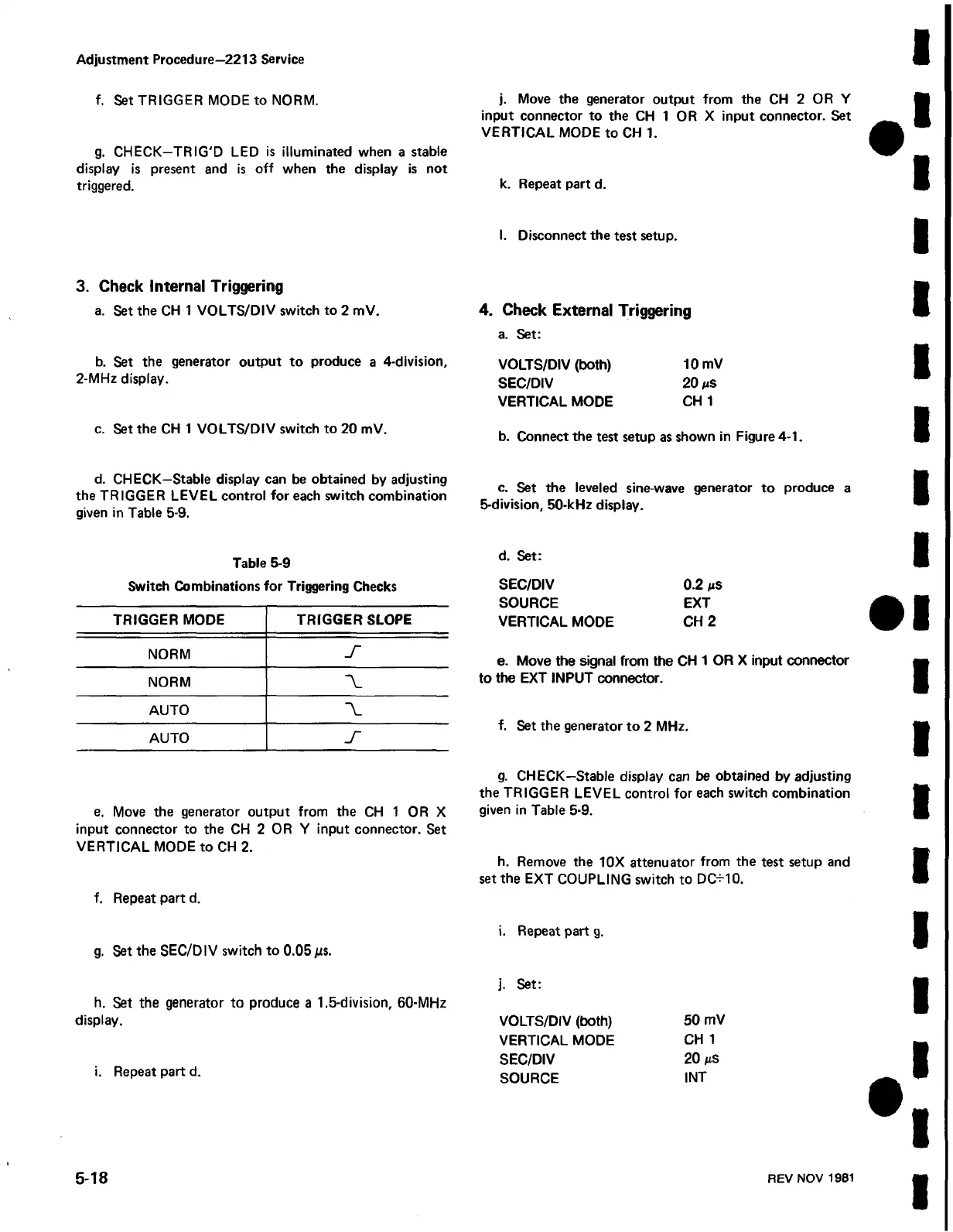
d. CHECK—Stable display can be obtained by adjusting
the TRIGGER LEVEL control for each switch combination
given in Table 5-9.
Table 5-9
Switch Combinations for Triggering Checks
TRIGGER MODE
TRIGGER SLOPE
NORM
S
NORM
■V
AUTO
AUTO
s
e. Move the generator output from the CH 1 OR X
input connector to the CH 2 OR Y input connector. Set
VERTICAL MODE to CH 2.
f. Repeat part d.
g. Set the SEC/DIV switch to 0.05 jus.
h. Set the generator to produce a 1.5-division, 60-MHz
display.
i. Repeat part d.
j. Move the generator output from the CH 2 OR Y
input connector to the CH 1 OR X input connector. Set
VERTICAL MODE to CH 1.
k. Repeat part d.
I. Disconnect the test setup.
4. Check External Triggering
a. Set:
VOLTS/DIV (both) 10 mV
SEC/DIV 20 ns
VERTICAL MODE CH 1
b. Connect the test setup as shown in Figure 4-1.
c. Set the leveled sine-wave generator to produce a
5-division, 50-kHz display.
d. Set:
SEC/DIV 0.2 #ts
SOURCE EXT
VERTICAL MODE CH 2
e. Move the signal from the CH 1 OR X input connector
to the EXT INPUT connector.
f. Set the generator to 2 MHz.
g. CHECK—Stable display can be obtained by adjusting
the TRIGGER LEVEL control for each switch combination
given in Table 5-9.
h. Remove the 10X attenuator from the test setup and
set the EXT COUPLING switch to DC-M0.
i. Repeat part g.
j. Set:
VOLTS/DIV (both) 50 mV
VERTICAL MODE CH 1
SEC/DIV 20 ms
SOURCE INT
5-18
REV NOV 1981
 Loading...


