EasyManua.ls Logo

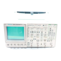
Tektronix 2247A

Tektronix 2247A
275 pages
To Next Page IconTo Next Page
To Previous Page IconTo Previous Page
Loading...
i
i
Performance
Check
Procedure
Table
7-1
Test
Equipment
Requlred
Item
and
Minimum
Example
of
Description
Specification
Use
Test
Equipment
Leveled
Frequency:
250
Vertical,
horl-
TEKTRONIX
Sine-Wave
kHz
to
above
150 zontal,
trigger-
|
SG
503
Leveled
Generator
MHz.
Output
am-
ing,
measure-
Sine-Wave
plitude:
variable
ment
bandwidth,
|
Generator
?
from
10
mV
to
and
Z-Axis
5
V
p-p.
Output
checks
and
Impedance:
50
1
adjustments.
Amplitude
Counter/Timer
accuracy:
con-
checks.
stant
within
1.5%
of
reference
frequency
to
100
MHz.
Calibration
Standard-
Signal
source
TEKTRONIX
Generator
amplitude
signal
for
gain
and
PG
506A
levels
(de
and
transient
re-
Calibration
square
wave):
sponse
checks
Generator.2
5
mV
to
50
V.
and
adjustments.
Accuracy:
+
0.25%.
High-amplitude
signal
levels:
1
V
to
60
V.
Repetition
rate:
1
kHz.
Fast-rise
signal
level:
1
V.
Repe-
tition
rate:
1
MHz.
Rise
time:
1
ns
or
less.
Flatness:
+0.5%.
Time-Mark
Markers:
Counter/Timer
TEKTRONIX
Generator
Snsto2sina
and
horizontal
TG
501
Option
1-2-5
sequence.
checks
and
01
(Precision
Accuracy:
adjustments.
Time
Base)
+
0,00005%,
Display
adjust-
|
Time-Mark
|
ment.
Time
Generator.
cursor
checks.
Function
Range:
less
than
Low-frequency
TEKTRONIX
Generator
1
Hz
to
1
kHz;
checks.
FG
502
sinusoidal
output;
Function
amplitude
variable
up
to
greater
than
10
V
p-p
open
circult
with
de
offset
adjust.
Generator
?
*
Requires
a
TM500-series
power
Module.
2247A
Operators
REV
SEP
1989

Related product manuals