EasyManua.ls Logo

Tektronix 2247A

Tektronix 2247A
275 pages
To Next Page IconTo Next Page
To Previous Page IconTo Previous Page
Loading...
J
a
|
i
3
ee
fg
Controls,
Connectors,
and
Indicators
course
LL LJ
couruma
sary
are
491?
Go
positigy
Position
mami
GAC
@
oc
7MNe
Ga
Oo
ay
£
a
Oo
00
o0
OO
fost
CH
Toe
EY
pints
S209
=
«COV
sl
oto
w\a
CH
2
CH3 CH4
M22
20pF
=
40054
2
M2006
=
400vo
N209F
=
400
eae
6373-04
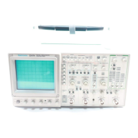
Figure
2-3.
Vertical
connectors
and
CH
3
and
CH
4
controls.
Auxillary
Ground
Jack—Provides
an
auxillary
chassis
ground
con-
nection
(banana
Jack)
between
the
equipment
under
test
and
the
2247A.
@1)
Channel
3
and
Channel
4
POSITION
Controls—Adjust
vertical
position
of
Channel
3
and
Channel
4
signal
displays.
@2)
Channel
3
and
Channel
4
VOLTS/DIV
Switches—Select
two
basic
deflection
factors
for
Channel
3
and
Channel
4,
0.5
volt/division
(but-
ton
lit)
or
0.1
voit/division
(button
not
lit).
The
VOLTS/DIV
switch
setting
displayed
In
the
crt
readout
reflects
the
attenuation
factor
of
coded
attenuator
probes
that
are
connected
to
the
vertical
inputs.
@3)
CH
3
and
CH
4
Input
Connectors—Connect
signals
to
the
inputs
of
the
Channel
3
and
Channel
4
vertical
attenuators.
Input
coupling
is
de
only.
The
Input
connectors
are
BNC
with
probe-coding
ring
contacts
(the
same
as
Channel
1
and
Channel
2).
The
limited
choice
of
deflection
factors
for
the
Channel
3
and
Channel
4
Inputs
makes
them
useful
for
digital
and
trigger
signals.
2247A
Operators
2-7

Related product manuals