CONTROLS AND CONNECTORS
Controls and connectors necessary for proper operation
of the instrument are located on the front, side, and rear
cabinet panels. To make full use of the capabilities o f this
instrument, the operator should be familiar with the func
tion and use of each external control and connector. A
brief description and use of each external control and con
nector is given herein
POWER SOURCE AND CONNECTORS
WARNING |
Change o f ac input voltage must be accom
plished by qualified service personnel only.
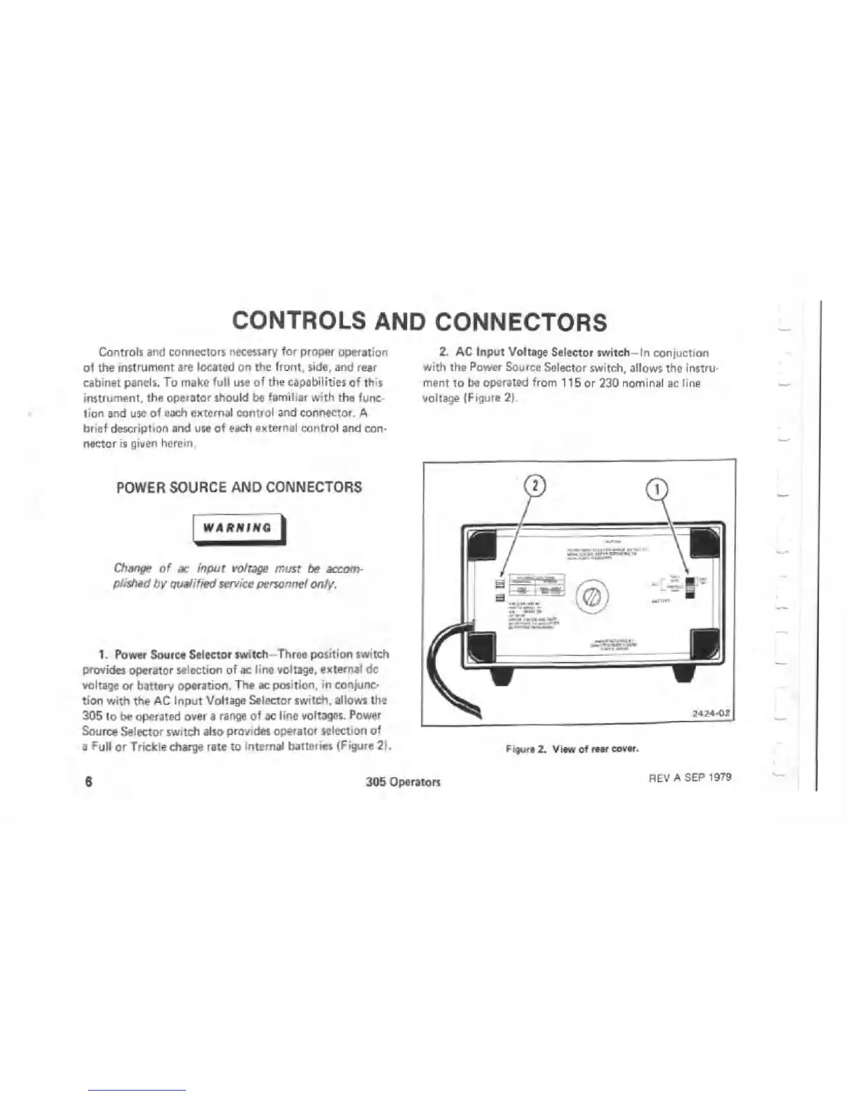
1. Power Source Selector switch-Three position switch
provides operator selection of ac line voltage, external dc
voltage or battery operation. The ac position, in conjunc
tion with the AC Input Voltage Selector switch, allows the
305 to be operated over a range of ac line voltages. Power
Source Selector switch also provides operator selection of
a Full or Trickle charge rate to internal batteries (Figure 21.
2. AC Input Voltage Selector switch-In conjuction
with the Power Source Selector switch, allows the instru
ment to be operated from 115 or 230 nominal ac line
voltage (Figure 2).
Figure 2. View o f rear cover.
6 305 Operators
REV A SEP 1979

 Loading...

