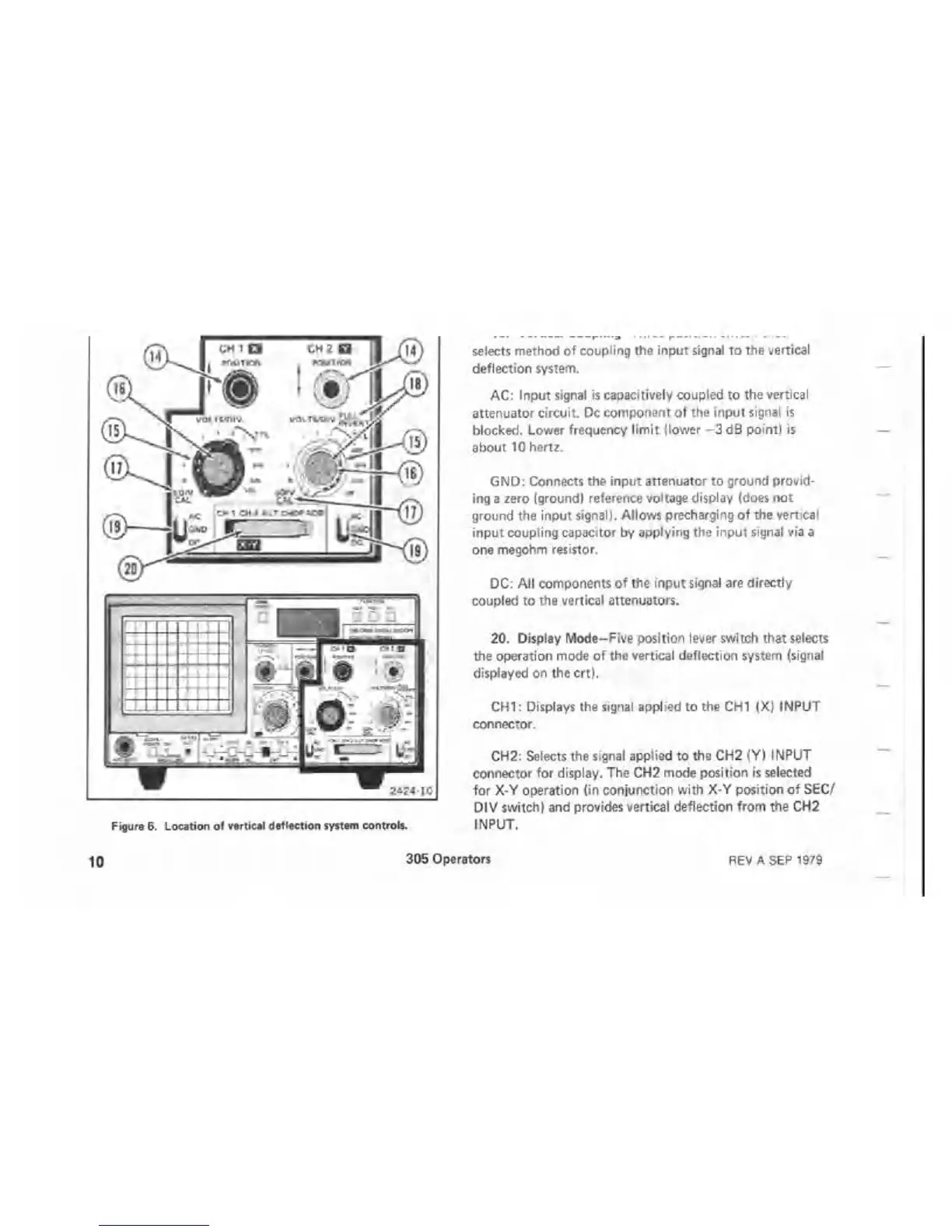
Figure 6. Location of vertical deflection system controls.
selects method of coupling the input signal to the vertical
deflection system.
AC: Input signal is capacitively coupled to the vertical
attenuator circuit. Dc component of the input signal is
blocked. Lower frequency lim it (lower —3 dB point) is
about 10 hertz.
GND: Connects the input attenuator to ground provid
ing a zero (ground) reference voltage display (does not
ground the input signal). Allows precharging of the vertical
input coupling capacitor by applying the input signal via a
one megohm resistor.
DC: All components of the input signal are directly
coupled to the vertical attenuators.
20. Display Mode-Five position lever switch that selects
the operation mode of the vertical deflection system (signal
displayed on the crt).
CHI: Displays the signal applied to the CHI (X) INPUT
connector.
CH2: Selects the signal applied to the CH2 (Y) INPUT
connector for display. The CH2 mode position is selected
for X-Y operation (in conjunction with X-Y position of SEC/
DIV switch) and provides vertical deflection from the CH2
INPUT.
10
305 Operators
REV A SEP 1979

 Loading...

