Maintenance—485/R485 Service
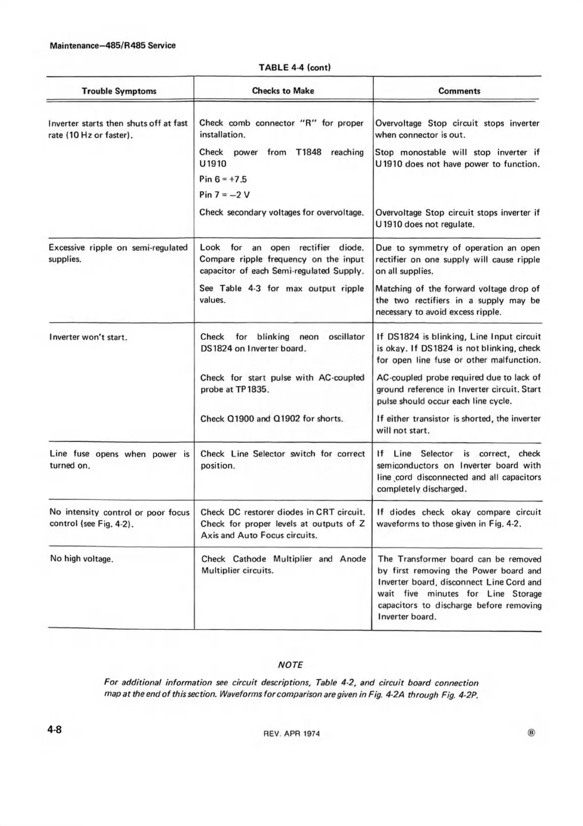
TABLE 4-4 (cont)
Trouble Symptoms
Checks to Make
Comments
1 nverter starts then shuts off at fast
rate (10 Hz or faster).
Check comb connector "R " for proper
installation.
Overvoltage Stop circuit stops inverter
when connector is out.
Check power from T1848 reaching
U1910
Stop monostable will stop inverter if
U1910 does not have power to function.
Pin 6 = +7.5
Pin 7 = -2 V
Check secondary voltages for overvoltage.
Overvoltage Stop circuit stops inverter if
U 1910 does not regulate.
Excessive ripple on semi-regulated
supplies.
Look for an open rectifier diode.
Compare ripple frequency on the input
capacitor of each Semi-regulated Supply.
Due to symmetry of operation an open
rectifier on one supply will cause ripple
on all supplies.
See Table 4-3 for max output ripple
values.
Matching of the forward voltage drop of
the two rectifiers in a supply may be
necessary to avoid excess ripple.
Inverter won't start.
Check for blinking neon oscillator
DS1824 on Inverter board.
If DS1824 is blinking. Line Input circuit
is okay. If DS1824 is not blinking, check
for open line fuse or other malfunction.
Check for start pulse with AC-coupled
probe at TP 1835.
AC-coupled probe required due to lack of
ground reference in Inverter circuit. Start
pulse should occur each line cycle.
Check Q1900 and Q1902 for shorts.
If either transistor is shorted, the inverter
will not start.
Line fuse opens when power is
turned on.
Check Line Selector switch for correct
position.
If Line Selector is correct, check
semiconductors on Inverter board with
line cord disconnected and all capacitors
completely discharged.
No intensity control or poor focus
control (see Fig. 4-2).
Check DC restorer diodes in CRT circuit.
Check for proper levels at outputs of Z
Axis and Auto Focus circuits.
If diodes check okay compare circuit
waveforms to those given in Fig. 4-2.
No high voltage. Check Cathode Multiplier and Anode
Multiplier circuits.
The Transformer board can be removed
by first removing the Power board and
Inverter board, disconnect Line Cord and
wait five minutes for Line Storage
capacitors to discharge before removing
Inverter board.
NOTE
For additional information see circuit descriptions, Table 4-2, and circuit board connection
map at the end o f this section. Waveforms for comparison are given in Fig. 4-2A through Fig. 4-2P.
4-8
REV. APR 1974