Maintenance—485/R485 Service
BALANCE NODE NOTE
The balance node (TP1951) acts as an "O R " circuit for various faults which w ill stop the inverter. To isolate the
fault, determine the voltage level at TP1951 during the 20 ms sampling period which immediately follows the
turn-on transient o f approximately 6 ms. If the balance node is more positive than +200 m V, look for a short on
a negative supply or over-current in the H. V. winding o f T1960. A H. V. current fault is present i f the voltage at
TP1958 (H.V.) goes positive during the sampling period, causing CR1958 to conduct. When observing power
supplies, check to see that each supply comes up to nominal value during the sampling period. If the balance node
is more negative than -2 0 0 m V, look for a short on a positive supply or high beam current. A beam lim it fault is
present i f the voltage at TP 1959 (LIM) goes negative during the sampling period causing CR1959 to conduct. A
fault in the vertical circuit (output leads shorted, etc.) w ill cause Q688 to crowbar the +25 V supply which stops
the inverter via the balance node. If the relays dick each time the inverter starts, some semi-regulated supplies are
briefly coming up to value. Look for a fault on +25 V, Beam Lim it Shutdown, or a short on one o f the regulated
supplies (+50, +9, —9, +5, or - 5 V).
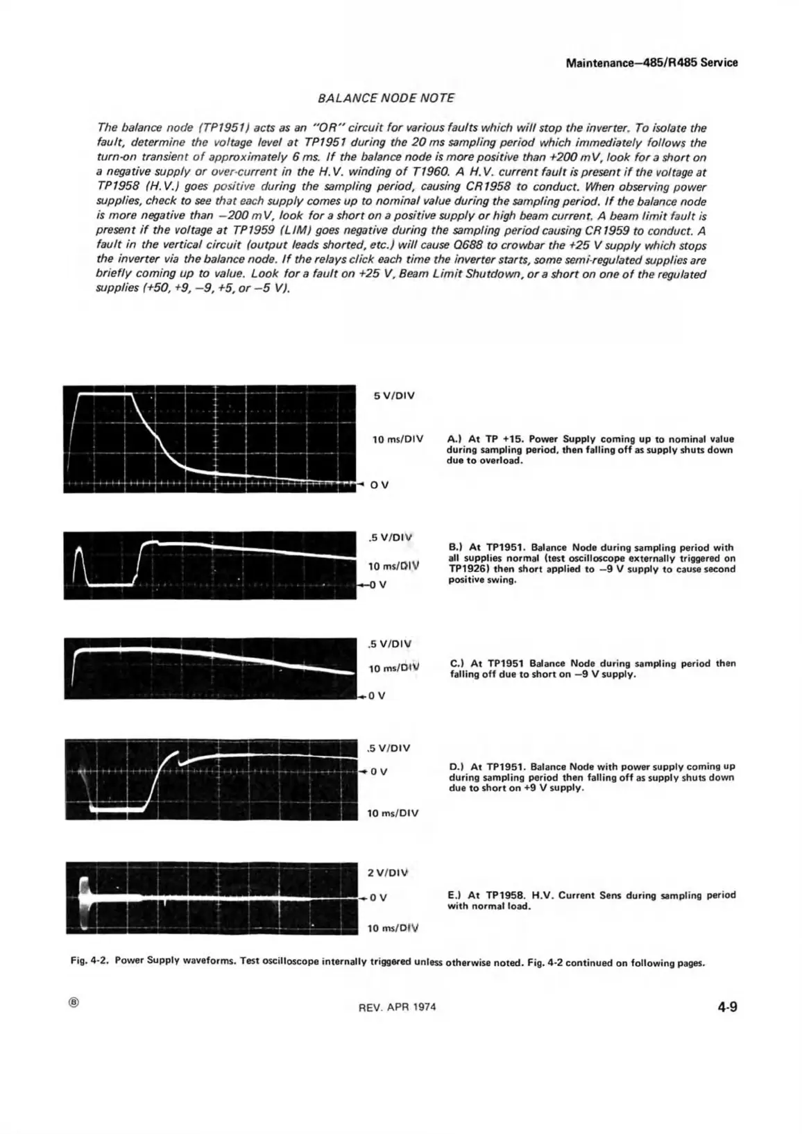
5 V/DIV
10 ms/DIV A.) A t TP +15. Power Supply coming up to nominal value
during sampling period, then falling o ff as supply shuts down
due to overload.
O V
B.) At TP1951. Balance Node during sampling period with
all supplies normal (test oscilloscope externally triggered on
TP1926) then short applied to -9 V supply to cause second
positive swing.
C.) At TP1951 Balance Node during sampling period then
falling off due to short on —9 V supply.
10 ms/DIV
5 V/D IV
0 V
D.) At TP1951. Balance Node with power supply coming up
during sampling period then falling off as supply shuts down
due to short on +9 V supply.
E.) At TP 1958. H.V. Current Sens during sampling period
with normal load.
Fig. 4-2. Power Supply waveforms. Test oscilloscope internally triggered unless otherwise noted. Fig. 4*2 continued on following pages.
CD
REV APR 1974
4-9