Calibration—485/R485 Service
3. ADJUST TRACE ROTATION
a. Position trace to graticule center.
b. Adjust TRACE ROTATION (rear panel) so trace
parallels the center graticule line.
4. CHECK B SWEEP TIMING ACCURACY
a. Check timing over center eight graticule divisions.
b. Position one time mark to 1 and read error at 9.
NOTE
+ 15°Cto +35° C
-15 °C to + 55 °C
1 ns to 20 ns; within 0.24
division (3%)
0.4 div (5%)
50 ns to 0.1 s; within 0.16
division (2%)
0.32 div (4%)
0.2 s and 0.5 s; within 0.24
division (3%)
0.4 div (5%)
5. CHECK A SWEEP TIM ING ACCURACY
NOTE
+ 15°Cto+35°C
— 75°C to +55° C
1 ns to 20 ns; within 0.24
division (3%)
0.4 div (5%)
50 ns to 0.1 s; within 0.16
division (2%)
0.32 div (4%)
0.2 s to 0.5 s; within 0.24
division (3%)
0.4 div (5%)
6. CHECK DELAY TIME ACCURACY, 10 ns/div
to 0.5 s/div (+15°C to +35°C only)
a. Use time marks that give 1 to 5 markers/div on the A
display. Use B TIME/DIV of 1 ns for A TIME/DIV settings
of 10 ns through 0.1 ps. For A TIME/DIV setting of 0.2 ps
and slower, maintain an A:B ratio of 100:1.
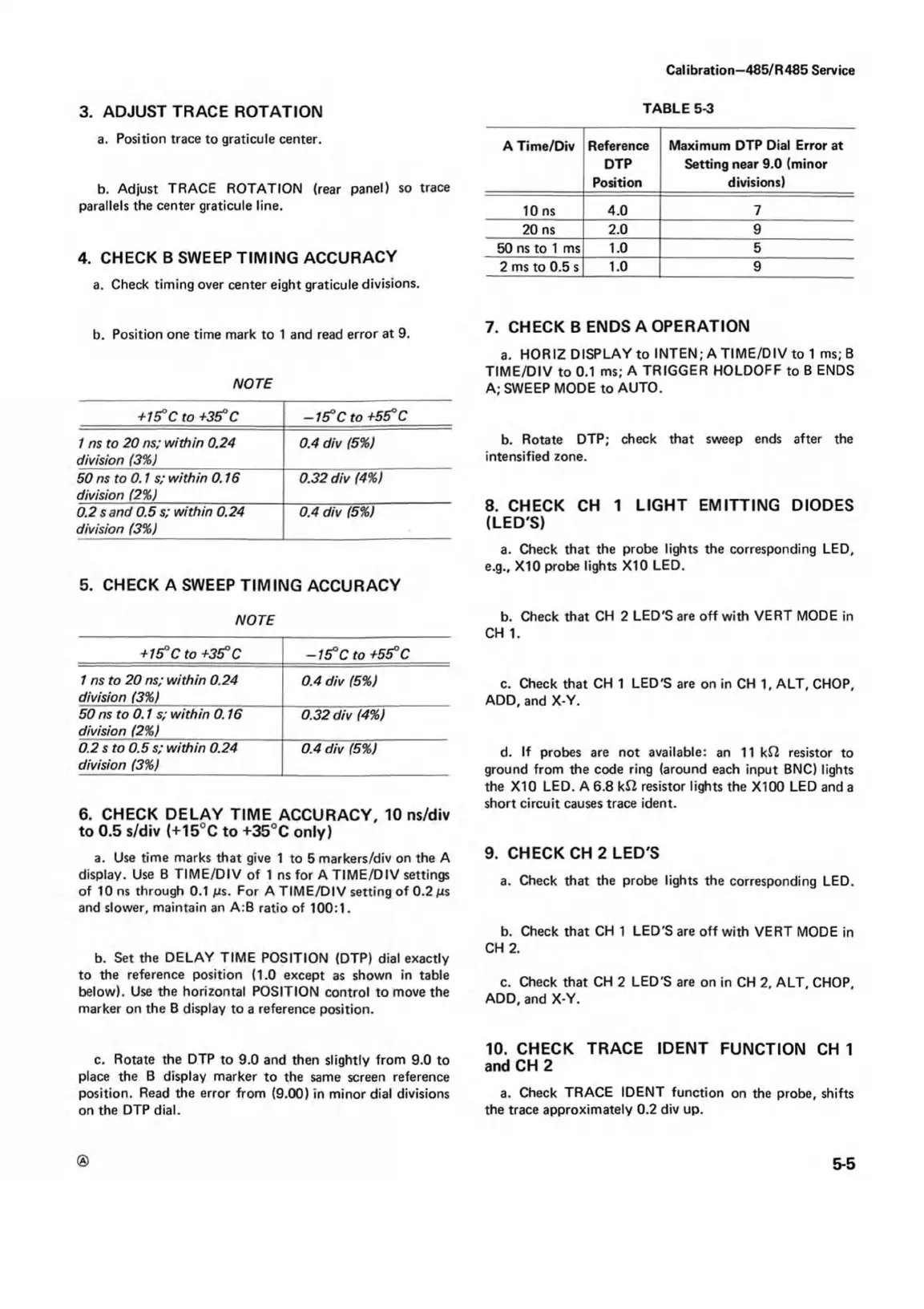
b. Set the DELAY TIME POSITION (DTP) dial exactly
to the reference position (1.0 except as shown in table
below). Use the horizontal POSITION control to move the
marker on the B display to a reference position.
c. Rotate the DTP to 9.0 and then slightly from 9.0 to
place the B display marker to the same screen reference
position. Read the error from (9.00) in minor dial divisions
on the DTP dial.
TABLE 5-3
A Time/Div
Reference
DTP
Position
Maximum DTP Dial Error at
Setting near 9.0 (minor
divisions)
10 ns
4.0
7
20 ns
2.0 9
50 ns to 1 ms
1.0 5
2 ms to 0.5 s
1.0 9
7. CHECK B ENDS A OPERATION
a. HORIZ DISPLAY to INTEN; A TIME/DIV to 1 ms; B
TIME/DIV to 0.1 ms; A TRIGGER HOLDOFF to B ENDS
A; SWEEP MODE to AUTO.
b. Rotate DTP; check that sweep ends after the
intensified zone.
8. CHECK CH 1 LIGHT EMITTING DIODES
(LED'S)
a. Check that the probe lights the corresponding LED,
e.g., X10 probe lights X10 LED.
b. Check that CH 2 LED'S are off with VERT MODE in
CH 1.
c. Check that CH 1 LED'S are on in CH 1, ALT, CHOP,
ADD, and X-Y.
d. If probes are not available: an 11 kJ2 resistor to
ground from the code ring (around each input BNC) lights
the X I0 LED. A 6.8 kJ2 resistor lights the X I00 LED and a
short circuit causes trace ident.
9. CHECK CH 2 LED'S
a. Check that the probe lights the corresponding LED.
b. Check that CH 1 LED'S are off with VERT MODE in
CH 2.
c. Check that CH 2 LED'S are on in CH 2, ALT, CHOP,
ADD, and X-Y.
10. CHECK TRACE IDENT FUNCTION CH 1
and CH 2
a. Check TRACE IDENT function on the probe, shifts
the trace approximately 0.2 div up.
5-5