Calibration—485/R485 Service
d. INTERACTION with 5 ns timing, repeat steps 26 and
27 if necessary.
31. ADJUST 1 ns TIMING
a. Set TIME/DIV to 1 ns.
b. Adjust 1 ns (R1228), (located in back of the lower
relay on the Sweep board) for exactly 1 to 9 timing (four
2 ns markers over the center 8 divisions).
c. If exact timing cannot be achieved, a compromise
adjustment may be done.
32. CHECK 1, 2, and 5 ns SWEEP LINEARITY
a. Less than 0.1 division of error with timing adjusted
on (1 ns through 20 ns). With time marks exactly aligned at
1 and 9 the remaining marks must be no greater than
0.1 div away from their respective graticule lines. The
incremental error must not exceed 0.1 div over any one
division.
33. CHECK B SWEEP TIM ING ACCURACY
a. Check timing over center 8 graticule divisions; posi
tion one time mark to 1 and read error at 9.
b. 1 ns to 20 ns;—within 0.16 div (2%).
c. 50 ns to 0.1 s;—within 0.1 div (1.25%).
d. 0.2 s to 0.5 s;—within 0.16 div (2%).
34. CHECK A SWEEP TIMING ACCURACY
a. 1 ns to 20 ns;—within 0.16 div (2%).
b. 50 ns to 0.1 s;—within 0.1 div (1.25%).
c. 0.2 s to 0.5 s;—within 0.16 div (2%).
35. CHECK AUTO REPETITION RATE
a. Set A TIME/DIV to 50 ms; SWEEP MODE to AUTO
TRIG.
b. Check that sweep triggers on 50 ms markers and will
not trigger on 0.1 s markers.
36. CHECK DELAY TIME ACCURACY, 10 ns/
div to 0.5 s/div
a. Use time marks that give 1 to 5 markers/div on the A
display. Use B TIME/DIV for 1 ns for A TIME/DIV settings
of 10 ns through 0.1 Ms. For A TIME/DIV setting of 0.2ms
and slower maintain an A:B ratio of 100:1.
b. Set the DTP dial exactly to the reference position
(1.0 except at the fastest speeds). Use the POSITION
(HORIZ) control to move the marker on the B display to a
reference position.
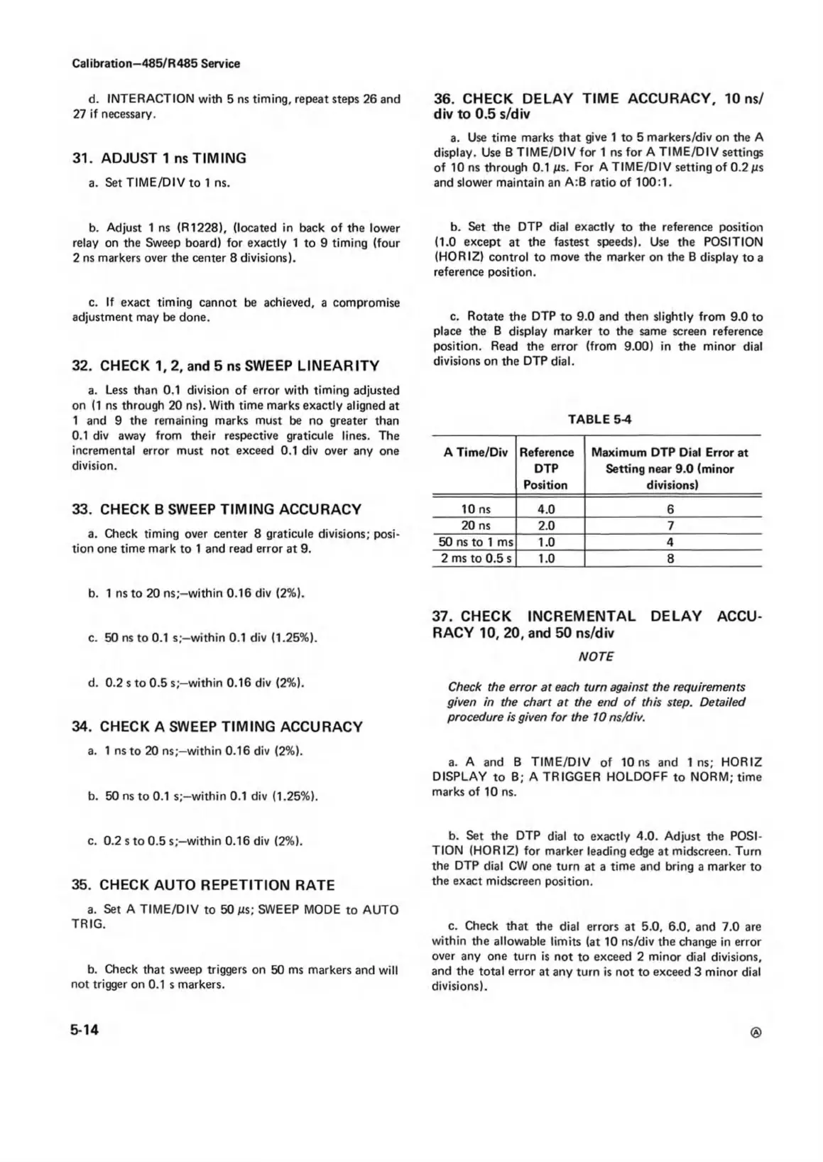
c. Rotate the DTP to 9.0 and then slightly from 9.0 to
place the B display marker to the same screen reference
position. Read the error (from 9.00) in the minor dial
divisions on the DTP dial.
TABLE 5-4
A Time/Div Reference
DTP
Position
Maximum DTP Dial Error at
Setting near 9.0 (minor
divisions)
10 ns
4.0 6
20 ns
2.0 7
50 ns to 1 ms
1.0
4
2 ms to 0.5 s 1.0
8
37. CHECK INCREMENTAL DELAY ACCU
RACY 10, 20, and 50 ns/div
NOTE
Check the error at each turn against the requirements
given in the chart at the end o f this step. Detailed
procedure is given for the 10 ns/div.
a. A and B TIME/DIV of 10ns and In s; HORIZ
DISPLAY to B; A TRIGGER HOLDOFF to NORM; time
marks of 10 ns.
b. Set the DTP dial to exactly 4.0. Adjust the POSI
TION (HORIZ) for marker leading edge at midscreen. Turn
the DTP dial CW one turn at a time and bring a marker to
the exact midscreen position.
c. Check that the dial errors at 5.0, 6.0, and 7.0 are
within the allowable limits (at 10 ns/div the change in error
over any one turn is not to exceed 2 minor dial divisions,
and the total error at any turn is not to exceed 3 minor dial
divisions).
5-14