Calibration—485/R485 Service
d. Set the DTP dial to exactly 6.0. Adjust the POSI
TION (HORIZ) for marker leading edge at midscreen. Turn
the DTP dial CW one turn at a time and bring a marker to
the exact midscreen position. Check that the dial errors at
7.0, 8.0, and 9.0 are within the allowable limits.
e. Use the same procedure to check the 20 ns and 50 ns
ranges.
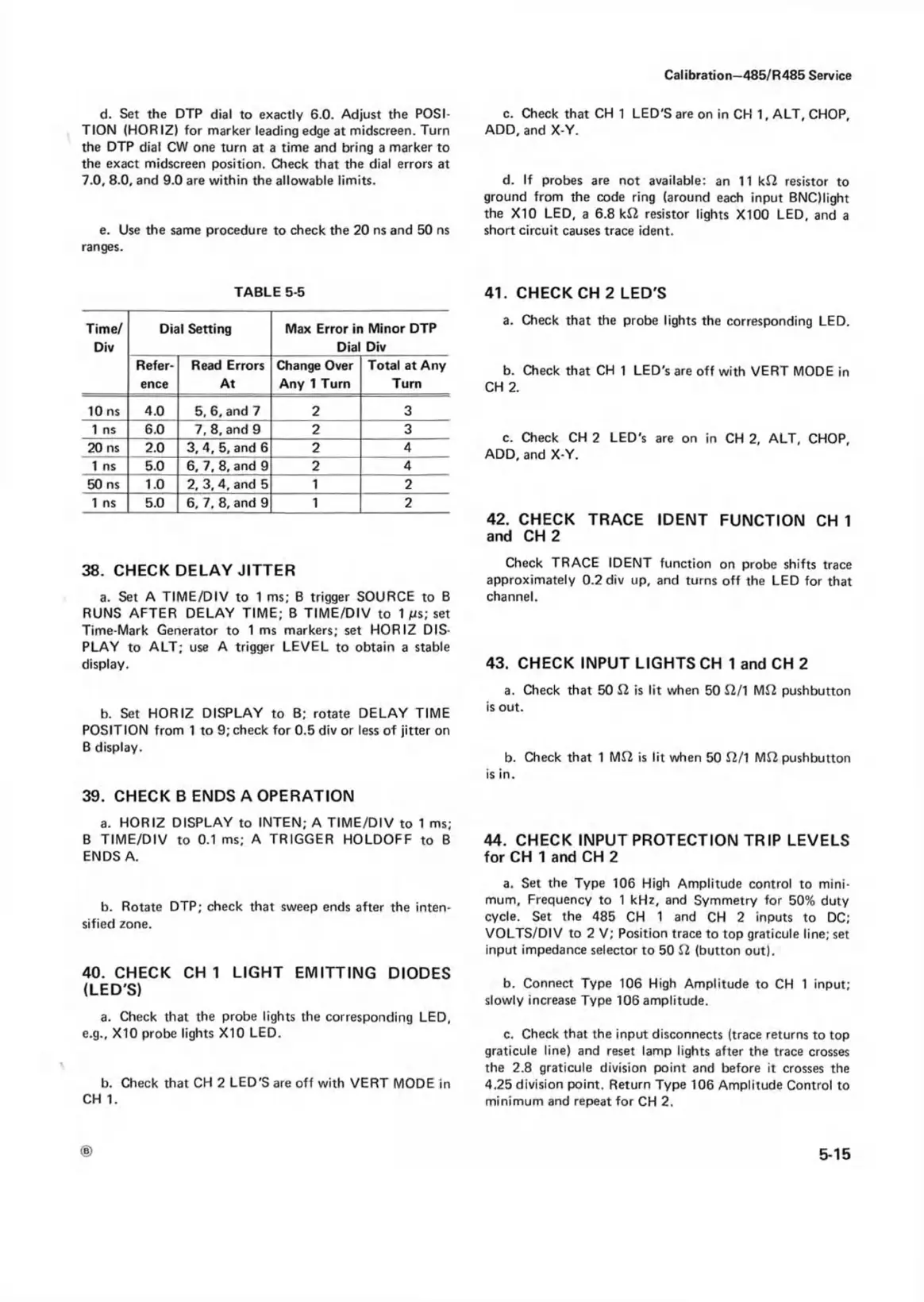
TABLE 5-5
Time/
Div
Dial Setting Max Error in Minor DTP
Dial Div
Refer
ence
Read Errors
At
Change Over
Any 1 Turn
Total at Any
Turn
10 ns 4.0 5, 6, and 7 2 3
1 ns
6.0 7, 8, and 9
2
3
20 ns 2.0 3, 4, 5, and 6 2
4
1 ns 5.0 6, 7, 8, and 9 2
4
50 ns 1.0 2, 3, 4, and 5 1
2
1 ns 5.0 6, 7, 8, and 9 1 2
38. CHECK DELAY JITTER
a. Set A TIME/DIV to 1 ms; B trigger SOURCE to B
RUNS AFTER DELAY TIME; B TIME/DIV to 1 /is; set
Time-Mark Generator to 1 ms markers; set HORIZ DIS
PLAY to ALT; use A trigger LEVEL to obtain a stable
display.
b. Set HORIZ DISPLAY to B; rotate DELAY TIME
POSITION from 1 to 9; check for 0.5 div or less of jitter on
B display.
39. CHECK B ENDS A OPERATION
a. HORIZ DISPLAY to INTEN; A TIME/DIV to 1 ms;
B TIME/DIV to 0.1 ms; A TRIGGER HOLDOFF to B
ENDS A.
b. Rotate DTP; check that sweep ends after the inten
sified zone.
40. CHECK C H I LIGHT EMITTING DIODES
(LED'S)
a. Check that the probe lights the corresponding LED,
e.g., X10 probe lights X10 LED.
b. Check that CH 2 LED'S are off with VERT MODE in
CH 1.
c. Check that CH 1 LED'S are on in CH 1, ALT, CHOP,
ADD, and X-Y.
d. If probes are not available: an 11 k£2 resistor to
ground from the code ring (around each input BNQIight
the X10 LED, a 6.8 k£2 resistor lights X100 LED, and a
short circuit causes trace ident.
41. CHECK CH 2 LED'S
a. Check that the probe lights the corresponding LED.
b. Check that CH 1 LED's are off with VERT MODE in
CH 2.
c. Check CH 2 LED's are on in CH 2, ALT, CHOP,
ADD, and X-Y.
42. CHECK TRACE IDENT FUNCTION CH 1
and CH 2
Check TRACE IDENT function on probe shifts trace
approximately 0.2 div up, and turns off the LED for that
channel.
43. CHECK INPUT LIGHTS CH 1 and CH 2
a. Check that 50 £2 is lit when 50 £2/1 M£2 pushbutton
is out.
b. Check that 1 M£2 is lit when 50 £2/1 M£2 pushbutton
is in.
44. CHECK INPUT PROTECTION TRIP LEVELS
for CH 1 and CH 2
a. Set the Type 106 High Amplitude control to mini
mum, Frequency to 1 kHz, and Symmetry for 50% duty
cycle. Set the 485 CH 1 and CH 2 inputs to DC;
VOLTS/DIV to 2 V; Position trace to top graticule line; set
input impedance selector to 50 £2 (button out).
b. Connect Type 106 High Amplitude to CH 1 input;
slowly increase Type 106 amplitude.
c. Check that the input disconnects (trace returns to top
graticule line) and reset lamp lights after the trace crosses
the 2.8 graticule division point and before it crosses the
4.25 division point. Return Type 106 Amplitude Control to
minimum and repeat for CH 2.
5-15