45. CHECK PROBE POWER
NOTE
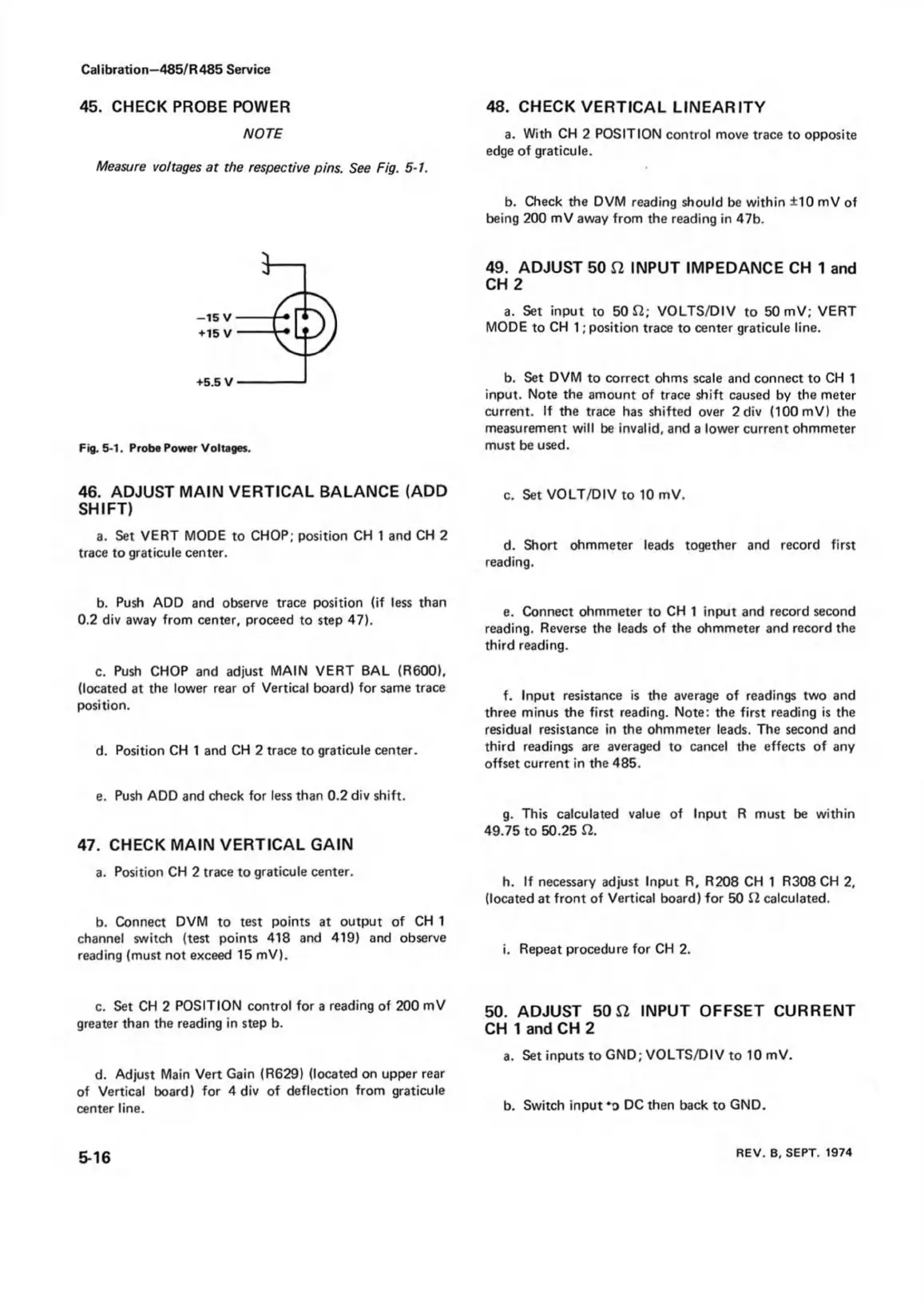
Measure voltages at the respective pins. See Fig. 5-1.
Calibration—485/R 485 Service
Fig. 5-1. Probe Power Voltages.
46. ADJUST MAIN VERTICAL BALANCE (ADD
SHIFT)
a. Set VERT MODE to CHOP; position CH 1 and CH 2
trace to graticule center.
b. Push ADD and observe trace position (if less than
0.2 div away from center, proceed to step 47).
c. Push CHOP and adjust MAIN VERT BAL (R600),
(located at the lower rear of Vertical board) for same trace
position.
d. Position CH 1 and CH 2 trace to graticule center.
e. Push ADD and check for less than 0.2 div shift.
47. CHECK MAIN VERTICAL GAIN
a. Position CH 2 trace to graticule center.
b. Connect DVM to test points at output of CH 1
channel switch (test points 418 and 419) and observe
reading (must not exceed 15 mV).
c. Set CH 2 POSITION control for a reading of 200 mV
greater than the reading in step b.
d. Adjust Main Vert Gain (R629) (located on upper rear
of Vertical board) for 4 div of deflection from graticule
center line.
48. CHECK VERTICAL LINEARITY
a. With CH 2 POSITION control move trace to opposite
edge of graticule.
b. Check the DVM reading should be within ±10 mV of
being 200 mV away from the reading in 47b.
49. ADJUST 50 ft INPUT IMPEDANCE CH 1 and
CH 2
a. Set input to 50 ft; VOLTS/DIV to 50 mV; VERT
MODE to CH 1; position trace to center graticule line.
b. Set DVM to correct ohms scale and connect to CH 1
input. Note the amount of trace shift caused by the meter
current. If the trace has shifted over 2 div (100 mV) the
measurement will be invalid, and a lower current ohmmeter
must be used.
c. Set VOLT/DIV to 10 mV.
d. Short ohmmeter leads together and record first
reading.
e. Connect ohmmeter to CH 1 input and record second
reading. Reverse the leads of the ohmmeter and record the
third reading.
f. Input resistance is the average of readings two and
three minus the first reading. Note: the first reading is the
residual resistance in the ohmmeter leads. The second and
third readings are averaged to cancel the effects of any
offset current in the 485.
g. This calculated value of Input R must be within
49.75 to 50.25 ft.
h. If necessary adjust Input R, R208 CH 1 R308 CH 2,
(located at front of Vertical board) for 50 S2 calculated.
i. Repeat procedure for CH 2.
50. ADJUST 50 ft INPUT OFFSET CURRENT
CH 1 and CH 2
a. Set inputs to GND; VOLTS/DIV to 10 mV.
b. Switch input *o DC then back to GND.
5-16
REV. B, SEPT. 1974