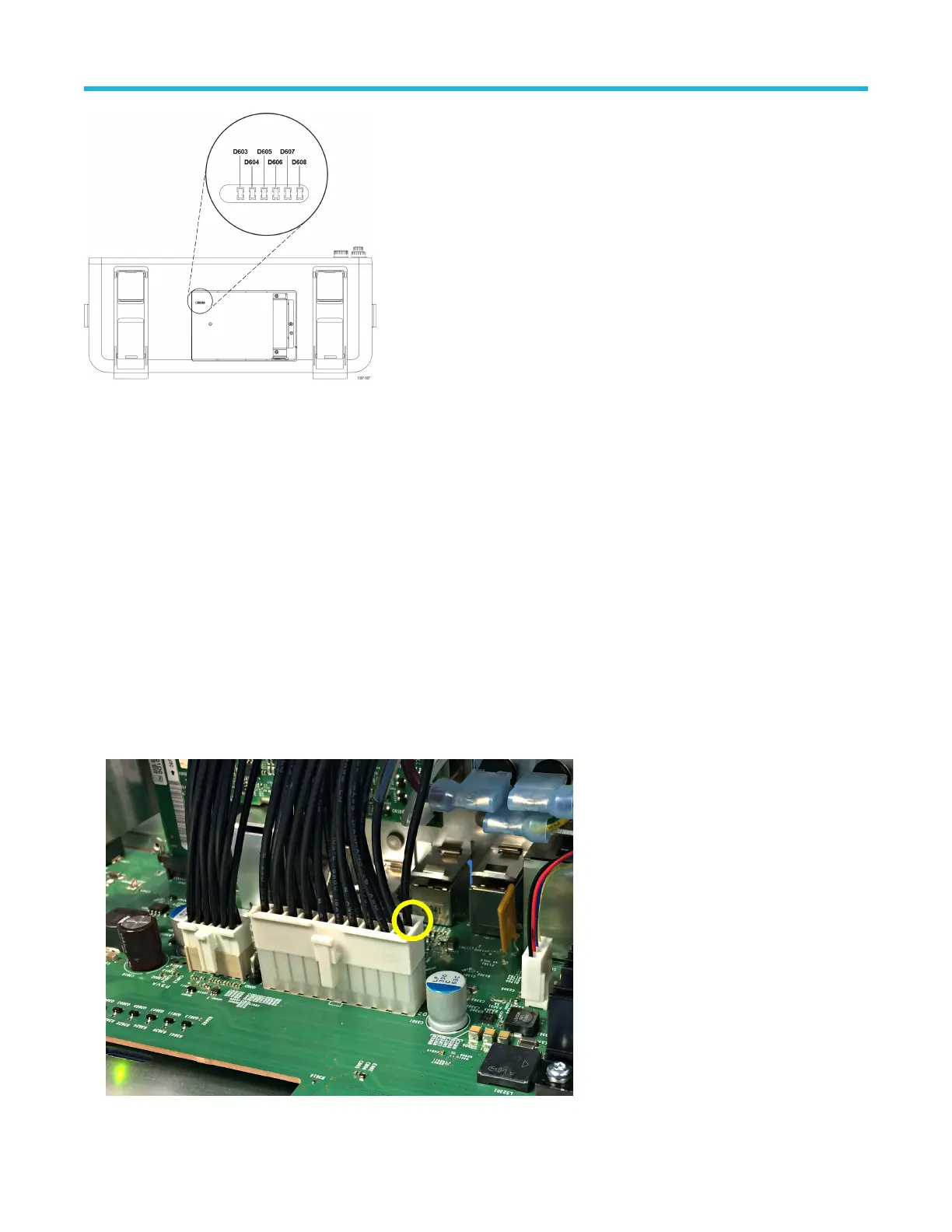
Figure 2: Power status LEDs
All of these LEDs should be green a few moments after powering on the instrument. If any of these LEDs are red, or are not lit, return the
instrument to a T
ektronix Service Center for repair.
Troubleshoot the power supply
Use this procedure to determine if the power supply is defective and needs replaced.
Before you begin
• To prevent electrostatic damage to components whenever you work on the instrument, wear properly-grounded electrostatic prevention
wrist and foot straps, and work in a tested antistatic environment on an antistatic mat.
• Remove rear chassis assembly on page 20
• Remove the baffle bracket on page 22
Procedure
1. Connect the power cord to the AC connector on the back of the rear chassis.
2. Measure for +12 V
DC
between chassis and pin 10 of J3203 (large connector). If there is +12 V
DC
at pin 10, go to step 3 on page 33. If
you do not measure +12 V
DC
at Pin 10 of J3203 connected to the circuit board:
Maintenance
5 Series Mixed Signal Oscilloscope MSO54, MSO56, MSO58 Service Manual 32

 Loading...


