c. Enter this value in the test record.
NOTE. For more information on the contents of this worksheet, refer to
the bandwidth specifications. (See Analog bandwidth 50 Ω DC coupled
on page 0 .)
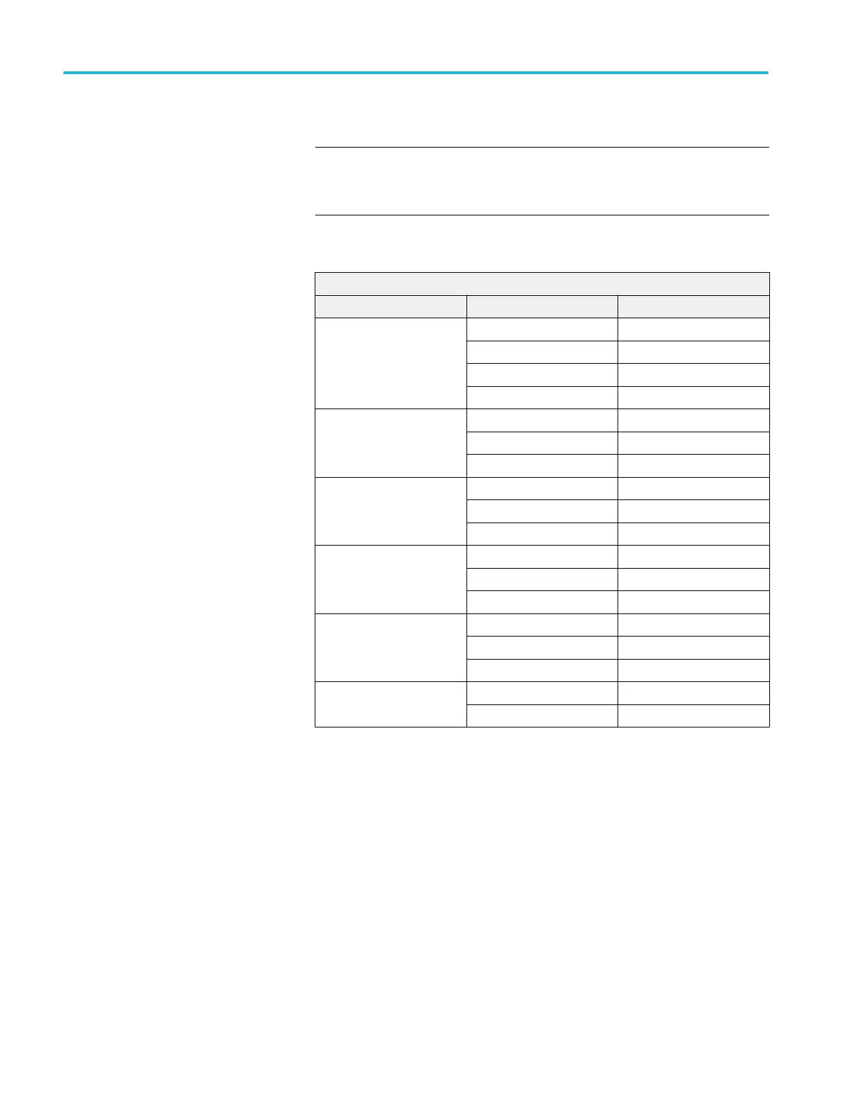
Table 23: Maximum bandwidth frequency worksheet
Model: MSO5204/B, DPO5204/B
Impedance Vertical Scale Maximum bandwidth
50 Ω 10 mV/div — 1 V/div 2 GHz
5 mV/div — 9.95 mV/div 1.5 GHz
2 mV/div — 4.98 mV/div 350 MHz
1 mV/div — 1.99 mV/div 175 MHz
1 MΩ 5 mV/div — 1 V/div 500 MHz, typical
2 mV/div — 4.98 mV/div 350 MHz, typical
1 mV/div — 1.99 mV/div 175 MHz, typical
50 Ω 5 mV/div — 1 V/div 1 GHz
2 mV/div — 4.98 mV/div 350 MHz
1 mV/div — 1.99 mV/div 175 MHz
1 MΩ 5 mV/div — 1 V/div 500 MHz, typical
2 mV/div — 4.98 mV/div 350 MHz, typical
1 mV/div — 1.99 mV/div 175 MHz, typical
50 Ω 5 mV/div — 1 V/div 500 MHz
2 mV/div — 4.98 mV/div 350 MHz
1 mV/div — 1.99 mV/div 175 MHz
50 Ω 2 mV/div — 1 V/div 350 MHz
1 mV/div — 1.99 mV/div 175 MHz
12. Use the values of Vbw-ppand Vin-ppstored in the test record to calculate the
Gain at bandwidth with the following equation:
Gain = Vbw-pp / Vin-pp
To pass the performance measurement test, Gain should be ≥ 0.707. Enter
Gain in the test record.
13. Repeat steps 4 through 12 for all combinations of Vertical Scale and
Horizontal Scale settings listed in the test record.
14. For MSO/DPO5204/B and MSO/DPO5104/B models only, repeat the tests at
1 MΩ impedance as follows:
a. Change the calibrator impedance to 1 MΩ.
b. Push the front-panel Vertical V menu button.
c. Set the Termination to 1 MΩ.
d. Repeat steps 4 through 13.
Performance verification (MSO/DPO5000/B series)
328 MSO70000C/DX, DPO70000C/DX, DPO7000C, MSO5000/B, DPO5000/B Series
 Loading...

